THEORY OF OPERATION
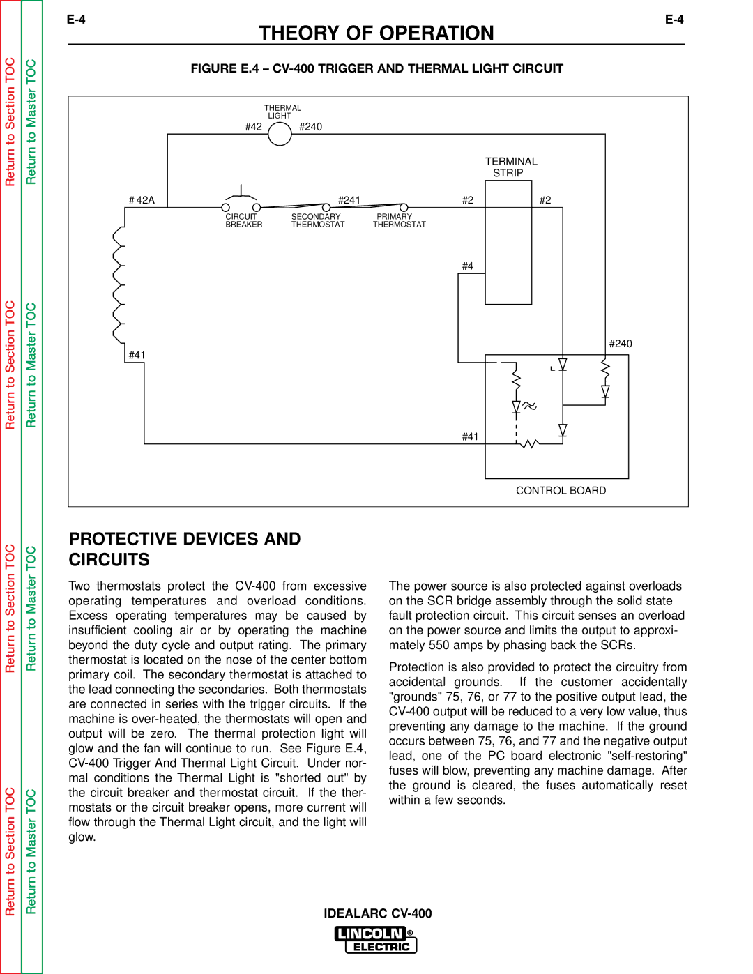
TOC | TOC | FIGURE E.4 – | |||
|
|
|
| ||
Section | Master |
| THERMAL |
|
|
| LIGHT |
|
| ||
#42 | #240 |
|
| ||
to | to |
|
| ||
|
|
|
| ||
Return | Return |
|
|
| TERMINAL |
|
|
| STRIP | ||
|
|
|
| ||
|
| # 42A | #241 | #2 | #2 |
|
| CIRCUIT | SECONDARY | PRIMARY |
|
|
| BREAKER | THERMOSTAT | THERMOSTAT |
|
|
|
|
| #4 |
|
TOC | TOC |
|
|
|
|
Return to Section | Return to Master | #41 |
|
| #240 |
|
|
| |||
|
| #41 |
| ||
|
|
|
|
| |
|
|
|
|
| CONTROL BOARD |
TOC | TOC | PROTECTIVE DEVICES AND |
|
| |
CIRCUITS |
|
| |||
Section | Master |
|
| ||
Two thermostats protect the | The power source is also protected against overloads | ||||
|
| ||||
|
| operating temperatures and overload conditions. | on the SCR bridge assembly through the solid state | ||
to | to | Excess operating temperatures may be caused by | fault protection circuit. This circuit senses an overload | ||
insufficient cooling air or by operating the machine | on the power source and limits the output to approxi- | ||||
Return | Return | ||||
beyond the duty cycle and output rating. The primary | Protection is also provided to protect the circuitry from | ||||
|
| mately 550 amps by phasing back the SCRs. | |||
|
| thermostat is located on the nose of the center bottom |
|
| |
|
| primary coil. The secondary thermostat is attached to | accidental grounds. | If the customer accidentally | |
|
| the lead connecting the secondaries. Both thermostats | |||
|
| "grounds" 75, 76, or 77 to the positive output lead, the | |||
|
| are connected in series with the trigger circuits. If the | |||
|
| ||||
|
| machine is | |||
|
| preventing any damage to the machine. If the ground | |||
|
| output will be zero. The thermal protection light will | |||
|
| occurs between 75, 76, and 77 and the negative output | |||
|
| glow and the fan will continue to run. See Figure E.4, | |||
|
| lead, one of the PC board electronic | |||
|
| ||||
|
| fuses will blow, preventing any machine damage. After | |||
|
| mal conditions the Thermal Light is "shorted out" by | |||
TOC |
| the ground is cleared, | the fuses automatically reset | ||
TOC | the circuit breaker and thermostat circuit. If the ther- | ||||
within a few seconds. |
| ||||
mostats or the circuit breaker opens, more current will |
| ||||
|
| ||||
SectiontoReturn | MastertoReturn | flow through the Thermal Light circuit, and the light will |
|
| |
|
|
|
| ||
|
| glow. |
|
| |
|
| IDEALARC |
| ||