Return to Section TOC
Return to Section TOC
Return to Section TOC
Return to Section TOC
Return to Master TOC
Return to Master TOC
Return to Master TOC
Return to Master TOC
| |||
TROUBLESHOOTING & REPAIR |
| ||
TROUBLESHOOTING GUIDE |
| Observe Safety Guidelines | |
| detailed in the beginning of this manual. | ||
|
|
| |
PROBLEMS | POSSIBLE AREAS OF | RECOMMENDED | |
(SYMPTOMS) | MISADJUSTMENT(S) | COURSE OF ACTION | |
|
|
|
|
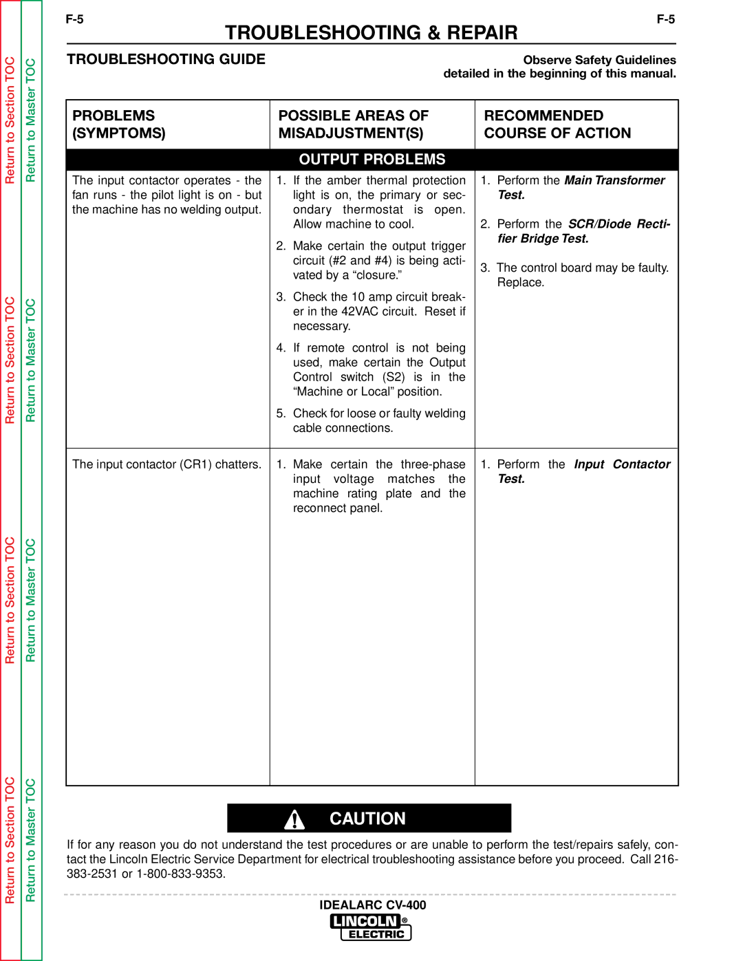
| OUTPUT PROBLEMS |
|
|
The input contactor operates - the | 1. If the amber thermal protection | 1. Perform the Main Transformer | |
fan runs - the pilot light is on - but | light is on, the primary or sec- | Test. | |
the machine has no welding output. | ondary thermostat is open. |
|
|
| Allow machine to cool. | 2. Perform the SCR/Diode Recti- | |
| 2. Make certain the output trigger | fier Bridge Test. | |
|
|
| |
| circuit (#2 and #4) is being acti- | 3. The control board may be faulty. | |
| vated by a “closure.” | ||
| Replace. | ||
|
| ||
| 3. Check the 10 amp circuit break- |
|
|
| er in the 42VAC circuit. Reset if |
|
|
| necessary. |
|
|
| 4. If remote control is not being |
|
|
| used, make certain the Output |
|
|
| Control switch (S2) is in the |
|
|
| “Machine or Local” position. |
|
|
| 5. Check for loose or faulty welding |
|
|
| cable connections. |
|
|
|
|
| |
The input contactor (CR1) chatters. | 1. Make certain the | 1. Perform the Input Contactor | |
| input voltage matches the | Test. | |
| machine rating plate and the |
|
|
| reconnect panel. |
|
|
|
|
|
|
CAUTION
If for any reason you do not understand the test procedures or are unable to perform the test/repairs safely, con- tact the Lincoln Electric Service Department for electrical troubleshooting assistance before you proceed. Call 216-