Section TOC
Master TOC
THEORY OF OPERATION
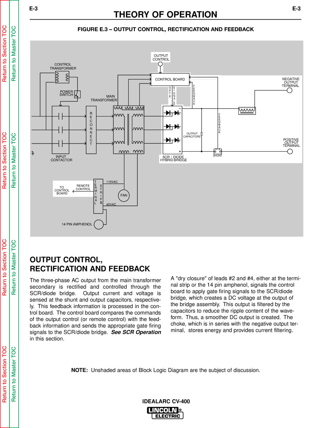
FIGURE E.3 – OUTPUT CONTROL, RECTIFICATION AND FEEDBACK
Return to
Return to Section TOC
Return to
Return to Master TOC
CONTROL
TRANSFORMER
POWER
SWITCH ![]() MAIN
MAIN
TRANSFORMER
R
E
C
O
N
N
E
C
T
INPUT
CONTACTOR
|
| T |
| 115VAC | |
TO | REMOTE | E | S |
|
|
CONTROL | R | T |
|
| |
CONTROL | M |
|
| ||
| R |
|
| ||
BOARD |
| I | FAN | ||
| I | ||||
|
| N | |||
|
| P |
|
| |
|
| LA |
|
| |
|
| s | 42VAC | ||
OUTPUT
CONTROL
CONTROL BOARD
|
|
|
|
|
|
|
|
|
|
| F |
|
|
| G | S |
|
|
|
| |||
|
|
|
|
|
|
| E | ||||
|
|
| A | I |
|
|
|
| |||
|
|
|
|
|
|
| E | ||||
|
|
| T | G |
|
|
|
| D | ||
|
|
| E | N |
|
|
|
| B | ||
|
|
|
|
| A |
|
|
|
| A | |
|
|
|
|
| L |
|
|
|
| C | |
|
|
|
|
| S |
|
|
|
| K | |
|
|
|
|
|
|
|
|
|
|
|
|
|
|
|
|
|
|
|
|
|
|
|
|
|
|
|
|
|
|
|
|
|
|
|
|
|
|
|
|
|
|
|
|
|
|
|
|
|
|
|
|
|
|
|
|
|
|
|
|
|
|
|
|
|
|
|
|
|
|
|
|
OUTPUT
CAPACITORS
SCR / DIODE
HYBRID BRIDGE
NEGATIVE
OUTPUT
TERMINAL
F
E
E
D
B
A
C
K
POSITIVE
OUTPUT
TERMINAL
SHUNT
14 PIN AMPHENOL
Return to Section TOC
Return to Master TOC
OUTPUT CONTROL, RECTIFICATION AND FEEDBACK
The
A "dry closure" of leads #2 and #4, either at the termi- nal strip or the 14 pin amphenol, signals the control board to apply gate firing signals to the SCR/diode bridge, which creates a DC voltage at the output of the bridge assembly. This output is filtered by the capacitors to reduce the ripple content of the wave- form. Thus, a smoother DC output is created. The choke, which is in series with the negative output ter- minal, stores energy and provides current filtering.
Return to Section TOC
Return to Master TOC
NOTE: Unshaded areas of Block Logic Diagram are the subject of discussion.