SR6004 SR5004
Important Safety Instructions
Table of Contents
Hdmi
Features
GUI
Before USE
Equipment Mains Working Setting
Do not Locate Following Places
Panel Door SR6004 only
Names and Function
Remote Control
Front Panel
¡0A-SURR
FL Display and Indicator
Remote Controller
Volume +/- buttons
Power on and OFF buttons
Spkr button
Zone a / B buttons
‹4LEARN indicator
¤6SETUP/MODE button
‹5MACRO indicator
‹6Information indicator
0AC
Rear Panel
1AC Outlets
Basic Connections
Speaker Placement
Height of the Speaker Units
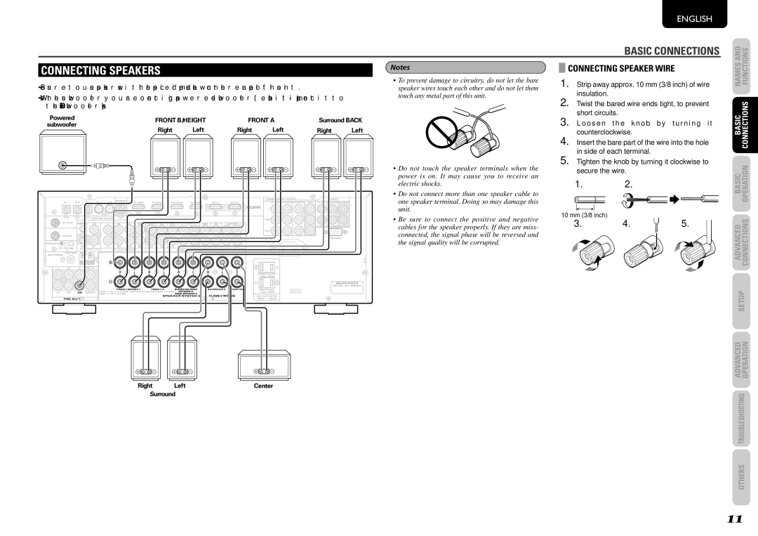
Connecting Speaker Wire
Connecting Speakers
Connecting Digital Audio Components
Connecting Audio Components
Source’s connected to digital input jacks
VIDEO, S-VIDEO, Component Jacks
Connecting Video Components
Video Jack
Component Jack
Connecting Hdmi Components
Connecting Hdmi Components
Hdmi Jacks
Connecting the AC Power Cable
Connecting the Antennas
Connecting the Supplied Antennas
Connecting AN Outdoor Antennas
AMP Operation
Basic Operation
Tuner Operation
AMP Mode
Remote Controller Operation
Tuner Mode
SR6004 SR5004
Advanced Connections
Connecting for Speaker C USE BI-AMP Connection
RX101
Connecting AN External Power Amplifier
Connecting Multi Channel Audio Components
Zone B
Connecting for Another Zone
Zone a
Connecting Other Equipment
Connecting the Remote Control Jacks
RS-232C
DC OUT DC Trigger
XM Satellite Radio
Connecting the Satellite Radio
Sirius Satellite Radio
Canada
Graphical User Interface GUI Menu System
Setup
Locking Submenus
RC007SR/RC008SR Button Control
Function Input Setup Assignable Digital Input
Input Setup
Default
7.1CH Input Setup
Function Rename
Space
Auto Setup Audyssey Multeq
Speaker Setup
Auto Setup
Manual Setup
Set the microphone in the main listening position
HOW to Perform Auto Setup Audyssey Multeq
Example
Example
Displayed Error Cause How to Remedy
Error Messages
Speakers Size
Manual Setup
LPF/HPF
Speakers Level
Speakers Distance
Channel Level
Surround Setup
Channel Level
Csii Parameter
PLIIx PRO Logic IIX Music Parameter
NEO6 Parameter
Video Setup
Preference
Zone Setup
DC Trigger Setup
Acoustic EQ
Check Audyssey Multeq
Adjust User EQ
Surround Mode
Selecting the Surround Mode
Display Mode
Auto Surround
Listening Through Headphones
Night Mode
Dolby Headphone Mode
DAX
Selecting Analog Audio Input or Digital Audio Input
Attenuation to Analog Input Signal
CH Input
Dual Backup Memory
Using the Sleep Timer
Recovery of Memory
LIP.SYNC
Video Convert
Hdmi Resolution
Convert
Hdmi OUT SR6004 only
Tuner Operation Preset Memory
Clearing Stored Preset Stations
Sorting Preset Stations
Name Input of the Preset Station
↔ B ↔ C ... Z ↔ 1 ↔ 2 ↔ 3 .... ↔ ↔ + ↔ / ↔ Blank ↔ a UP ↔
Satellite Radio Overview
Checking the XM Signal Strength and Radio ID
Listening to XM Satellite Radio
Listening to Satellite Radio
O O O R a D I O I D
Switching XM Information in the Front Panel Display
O 4 6 T o p T r a O p T r a c k s
M E / T I T L E
Category Search Mode
Preset channel can be checked on the on screen display
Checking the XM Preset Channel
Channel Direct Call
0 4
Clearing Stored Preset Channels
Checking the Sirius Signal Strength and Radio ID
Listening to Sirius Satellite Radio
M E / T I T L E O i d N e y
Switching Sirius Information in the Front Panel Display
O O O S i r i u s I D
0 2
ALL Channel Search Mode
Search Mode
Preset Search Mode
R 0 4
Parental Lock
SETTING/RELEASING Parental Lock
S W O R D O K 0 0 1 7a b c d e f g
S W O R D 9 9 9 W W O R D
When NEW Word is displayed
Preparations for USB Operation
Remote Controller
What Appears on the FL Display
→ U S B
Playing Files on the USB Media
Connecting USB Media
What Appears on the Monitor Screen File List
Icon Displays
Playing Specific Parts Search
Playing Tracks AT Random Random Play
Listening to Files Repeatedly Repeat Play
Preparations for iPod Operation Using the unit
Viewing the Status Screen
Connecting the iPod
What Appears on the Monitor Screen
Changing the Operation Mode of the iPod
Remote Mode
Playing Tracks on the iPod
Repeat Play
Supported Media USB
Status Displays
File Systems Supported USB
E R C U R R E N T
About iPod Play Back
Playable File Formats USB
Character
Standard Range supported
Zone Playback Using the Zone Speaker a Terminals
Zone Playback Using the Zone OUT Terminals
Zone System
Controlling a Marantz DVD DVD Mode
Controlling a Marantz BD BD Mode
Controlling a Marantz CD CD Mode
Controlling a Marantz DSS DSS Mode
Corsor
BASS/CH
Controlling a Marantz RX101 M-XP Mode
Controlling a Marantz TV TV Mode
Pause Play Stop
Preset Mode
SR6004 Remote Controller Basic Operation
Normal Mode
Setting the Back Light
Learn Mode
Resetting the Code
Learning Procedure
Checking the Code
Erasing Programmed Codes
Returning to Initial Settings
Erasing the Code by Source
Erasing the ALL Sources
Programming Macros
SR6004 Remote Controller Macro Mode
Confirming Macros
Program Method of Macro
Editing Macros
Using Macros
Examples of Macro Programs
Example
Now, execute the macro you just programmed
AMP → Power on DVD → Power on
AMP → DVD DVD → Play
Clearing Macro Programs
Adjusting the Interval Time of Macro Operations Transmitting
When operating non-Marantz AV equipment products
SR5004 Remote Controller Basic Operation
Preset code
Checking the Code
Select the button to be learned Learn indicator lights up
Erasing Programmed Codes Returning to Initial Settings
Erasing the code by buttons
Erasing the code by Source
Symptom Cause Solution
Troubleshooting
Enable
General
Stereo
Surround
Video
Not enabled when the unit is
Hdmi
Or component as the source
USB SR6004 only
Tuner
Front KEY Button Lock of the Unit
XM Satellite Radio
General Malfunction
Others
Surround Mode
SubW Subwoofer LFE Low frequency efects ex Extension
Others
Source Direct
Auto
EX/ES
Mode
Circle Surround
Description
Stereo
Multi CH. MOVIE, Music
Dts Neo6
Dts Digital Surround
Dts Digital Surround ES
Dts Digital Surround 96/24
About Dolby Pro Logic
Macrovision
MultEQ
Dynamic VolumeTM
SIRIUS, XM Satellite Radio Ready
Available in Alaska and Hawaii
Copyright
Technical Specifications
Repairs
DVD
Setup Codes
DSS
1001
1110, 1112, 1133
1024
1003, 1052, 1053, 1056
Dimensions
Is a registered trademark