7521Plus / N N/B MAINTENANCE
5.Pin Descriptions Of Major Components
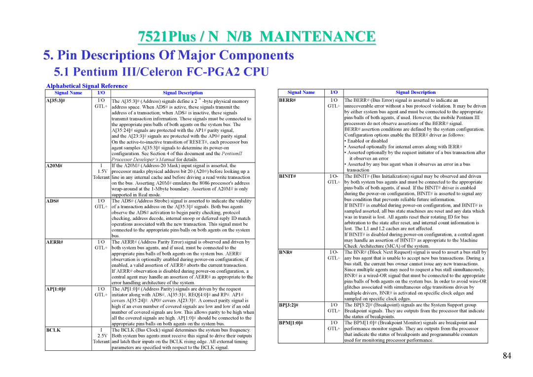
5.1Pentium III/Celeron FC-PGA2 CPU
Alphabetical Signal Reference
Signal Name | I/O | Signal Description |
A[35:3]# | I/O | The A[35:3]# (Address) signals define a 2 36 |
| GTL+ | address space. When ADS# is active, these signals transmit the |
|
| address of a transaction; when ADS# is inactive, these signals |
|
| transmit transaction information. These signals must be connected to |
|
| the appropriate pins/balls of both agents on the system bus. The |
|
| A[35:24]# signals are protected with the AP1# parity signal, |
|
| and the A[23:3]# signals are protected with the AP0# parity signal. |
|
| On the |
|
| agent samples A[35:3]# signals to determine its |
|
| configuration. See Section 4 of this document and the PentiumII |
|
| Processor Developer’s Manual for details. |
A20M# | I | If the A20M# |
| 1.5V | processor masks physical address bit 20 (A20#) before looking up a |
| Tolerant | line in any internal cache and before driving a read/write transaction |
|
| on the bus. Asserting A20M# emulates the 8086 processor's address |
|
| |
|
| supported in Real mode. |
ADS# | I/O | The ADS# (Address Strobe) signal is asserted to indicate the validity |
| GTL+ | of a transaction address on the A[35:3]# signals. Both bus agents |
|
| observe the ADS# activation to begin parity checking, protocol |
|
| checking, address decode, internal snoop or deferred reply ID match |
|
| operations associated with the new transaction. This signal must be |
|
| connected to the appropriate pins/balls on both agents on the system |
|
| bus. |
AERR# | I/O | The AERR# (Address Parity Error) signal is observed and driven by |
| GTL+ | both system bus agents, and if used, must be connected to the |
|
| appropriate pins/balls of both agents on the system bus. AERR# |
|
| observation is optionally enabled during |
|
| enabled, a valid assertion of AERR# aborts the current transaction. |
|
| If AERR# observation is disabled during |
|
| central agent may handle an assertion of AERR# as appropriate to the |
|
| error handling architecture of the system. |
AP[1:0]# | I/O | The AP[1:0]# (Address Parity) signals are driven by the request |
| GTL+ | initiator along with ADS#, A[35:3]#, REQ[4:0]# and RP#. AP1# |
|
| covers A[35:24]#. AP0# covers A[23:3]#. A correct parity signal is |
|
| high if an even number of covered signals are low and low if an odd |
|
| number of covered signals are low. This allows parity to be high when |
|
| all the covered signals are high. AP[1:0]# should be connected to the |
|
| appropriate pins/balls on both agents on the system bus. |
BCLK | I | The BCLK (Bus Clock) signal determines the system bus frequency. |
| 2.5V | Both system bus agents must receive this signal to drive their outputs |
| Tolerant | and latch their inputs on the BCLK rising edge. All external timing |
|
| parameters are specified with respect to the BCLK signal. |
Signal Name | I/O | Signal Description |
BERR# | I/O | The BERR# (Bus Error) signal is asserted to indicate an |
| GTL+ | unrecoverable error without a bus protocol violation. It may be driven |
|
| by either system bus agent and must be connected to the appropriate |
|
| pins/balls of both agents, if used. However, the mobile Pentium III |
|
| processors do not observe assertions of the BERR# signal. |
|
| BERR# assertion conditions are defined by the system configuration. |
|
| Configuration options enable the BERR# driver as follows: |
|
| • Enabled or disabled |
|
| • Asserted optionally for internal errors along with IERR# |
|
| • Asserted optionally by the request initiator of a bus transaction after |
|
| it observes an error |
|
| • Asserted by any bus agent when it observes an error in a bus |
|
| transaction |
BINIT# | I/O- | The BINIT# (Bus Initialization) signal may be observed and driven |
| GTL+ | by both system bus agents and must be connected to the appropriate |
|
| pins/balls of both agents, if used. If the BINIT# driver is enabled |
|
| during the |
|
| bus condition that prevents reliable future information. |
|
| If BINIT# is enabled during |
|
| sampled asserted, all bus state machines are reset and any data which |
|
| was in transit is lost. All agents reset their rotating ID for bus |
|
| arbitration to the state after reset, and internal count information is |
|
| lost. The L1 and L2 caches are not affected. |
|
| If BINIT# is disabled during |
|
| may handle an assertion of BINIT# as appropriate to the Machine |
|
| Check Architecture (MCA) of the system. |
BNR# | I/O- | The BNR# (Block Next Request) signal is used to assert a bus stall by |
| GTL+ | any bus agent that is unable to accept new bus transactions. During a |
|
| bus stall, the current bus owner cannot issue any new transactions. |
|
| Since multiple agents may need to request a bus stall simultaneously, |
|
| BNR# is a |
|
| pins/balls of both agents on the system bus. In order to avoid |
|
| glitches associated with simultaneous edge transitions driven by |
|
| multiple drivers, BNR# is activated on specific clock edges and |
|
| sampled on specific clock edges. |
BP[3:2]# | I/O | The BP[3:2]# (Breakpoint) signals are the System Support group |
| GTL+ | Breakpoint signals. They are outputs from the processor that indicate |
|
| the status of breakpoints. |
BPM[1:0]# | I/O | The BPM[1:0]# (Breakpoint Monitor) signals are breakpoint and |
| GTL+ | performance monitor signals. They are outputs from the processor |
|
| that indicate the status of breakpoints and programmable counters |
|
| used for monitoring processor performance. |
84