7521Plus / N N/B MAINTENANCE
5.Pin Descriptions Of Major Components
5.2SiS630S Slot 1/Socket 370 2D/3D Ultra-AGP™ Single Chipset
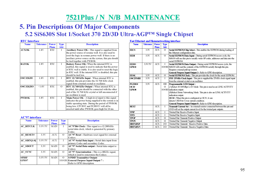
RTC Interface
Name | Tolerance | Power | Type | Description |
|
| Plane | Attr |
|
AUXOK | 1.8V | RTC | I | Auxiliary Power OK : This signal is supplied from |
|
|
|
| the power source of resume well. It is also used to |
|
|
|
| reset the logic in resume power well. If there is no |
|
|
|
| auxiliary power source on the system, this pin should |
|
|
|
| be tied together with PWROK. |
BATOK | 1.8V | RTC | I | Battery Power OK: When the internal RTC is |
|
|
|
| enabled, this signal is used to indicate that the power |
|
|
|
| of RTC well is stable. It is also used to reset the logic |
|
|
|
| in RTC well. If the internal RTC is disabled, this pin |
|
|
|
| should be tied low. |
OSC32KHI | 1.8V | RTC | I | RTC 32.768 KHz Input : When internal RTC is |
|
|
|
| enabled, this pin provides the 32.768 KHz clock |
|
|
|
| signal from external crystal or oscillator. |
OSC32KHO | <1.8V | RTC | O | RTC 32.768 KHz Output : When internal RTC is |
|
|
|
| enabled, this pin should be connected with the other |
|
|
|
| end of the 32.768 KHz crystal or left unconnected if |
|
|
|
| an oscillator is used. |
PWROK | 1.8V | RTC | I | Main Power OK : A |
|
|
|
| indicates the power being supplied to the system is in |
|
|
|
| stable operating state. During the period of PWROK |
|
|
|
| being low, CPURST and PCIRST# will all be |
|
|
|
| asserted until after PWROK goes high for 24 ms. |
AC’97 interface
Name | Tolerance | Power | Type | Description |
|
| Plane | Attr |
|
AC_BITCLK | 3.3V/5V | MAIN | I | AC’97Bit Clock : This signal is a 12.288MHz |
|
|
|
| serial data clock, which is generated by primary |
|
|
|
| Codec. |
AC_RESET# | 3.3V | AUX | O | AC’97 Reset : Hardware reset signal for external |
|
|
|
| Codecs. |
AC_SDIN[1:0] | 3.3V/5V | AUX | I | AC’97 Serial Data input : Serial data input from |
|
|
|
| primary Codec and secondary Codec. |
AC_SDOUT | 3.3V | MAIN | O | AC’97 Serial Data output : Serial data output to |
|
|
|
| Codecs. |
AC_SYNC | 3.3V | MAIN | O | AC’97 Syncronization : This is a 48KHz signal, |
|
|
|
| which is used to syncronize the Codecs. |
SPDIF | 3.3V/5V | MAIN | O | S/PDIF Transmitter Output |
GPIO7 |
|
| I/O/OD | General Purpose Input/Output 7 : |
|
|
|
| Refer to GPIO description. |
Fast Ethernet and Homenetworking interface
Name | Tolerance | Power | Type | Description |
|
| Plane | Attr |
|
EECS | 3.3V | AUX | O | Serial EEPROMChip Select : This enables the EEPROMduring loading of |
|
|
|
| the Ethernet configuration data. |
EEDI | 3.3V | AUX | O | Serial EEPROMData Input : During serial EEPROMaccess cycle, the |
|
|
|
| SiS630 will use this pin to serially write OP codes, addresses and data into the |
|
|
|
| serial EEPROM. |
EEDO | 3.3V/5V | AUX | I | Serial EEPROMData Output : During serial EEPROMaccess cycle, the |
GPIO3 |
|
| I/O/OD | SiS630 will read the contents of the EEPROMserially through this pin. |
|
|
|
| Requires external |
|
|
|
| General Purpose Input/Output 3 : Refer to GPIO description. |
EESK | 3.3V | AUX | O | Serial EEPROMClock : This pin provides the clock for the serial EEPROM. |
OSC25MHI | 3.3V | AUX | I | PHY25MHz Clock Input : This pin is supplied the 25MHz clock signal input |
|
|
|
| fromthe external crystal or an oscillator. |
PLEDO# | 3.3V | AUX | OD | Programmable LED Output : |
OC3# |
|
| O | (A)Select 10/100Mbps LANMode: This pin is used as an LINK/ACTIVITY |
GPIO8 |
|
| I/O/OD | indication output. |
|
|
|
| (B)Select Home Networking Mode: This pin is also an LINK/ACTIVITY |
|
|
|
| indication output. |
|
|
|
| OC3# : When this pin is configured as OC3#, it can |
|
|
|
| detects USB Port 3 over current condition. |
|
|
|
| General Purpose Input/Output 8 : Refer to GPIO description. |
REXT |
| AUX | I | Transmit Current Set : An external resistor connected between this pin and |
|
|
|
| GND will set the output current level for the twisted pair outputs. |
TPIP |
| AUX | I | Twisted Pair Receive Positive Input |
TPIN |
| AUX | I | Twisted Pair Receive Negative Input |
TPOP |
| AUX | O | Twisted Pair Transmit Positive Output |
TPON |
| AUX | O | Twisted Pair Transmit Negative Output |
HRTXRXP |
| AUX | I/O | Twisted Pair Transmit / Receive Positive Data |
HRTXRXN |
| AUX | I/O | Twisted Pair Transmit / Receive Negative Data |
95
