Manuals
/
MiTAC
/
Computer Equipment
/
Laptop
MiTAC
7521 PLUS/N
service manual
Hot Key Function Easy Start Button function
Models:
7521 PLUS/N
1
38
180
180
Download
180 pages
51.44 Kb
35
36
37
38
39
40
41
42
Troubleshooting
Parts list
Plus/N Schematics
Bit free-running timer
LED Indicators
Maintenance
Symptom
Reset#
Diagnostic Tools
HDD & Video access
Page 38
Image 38
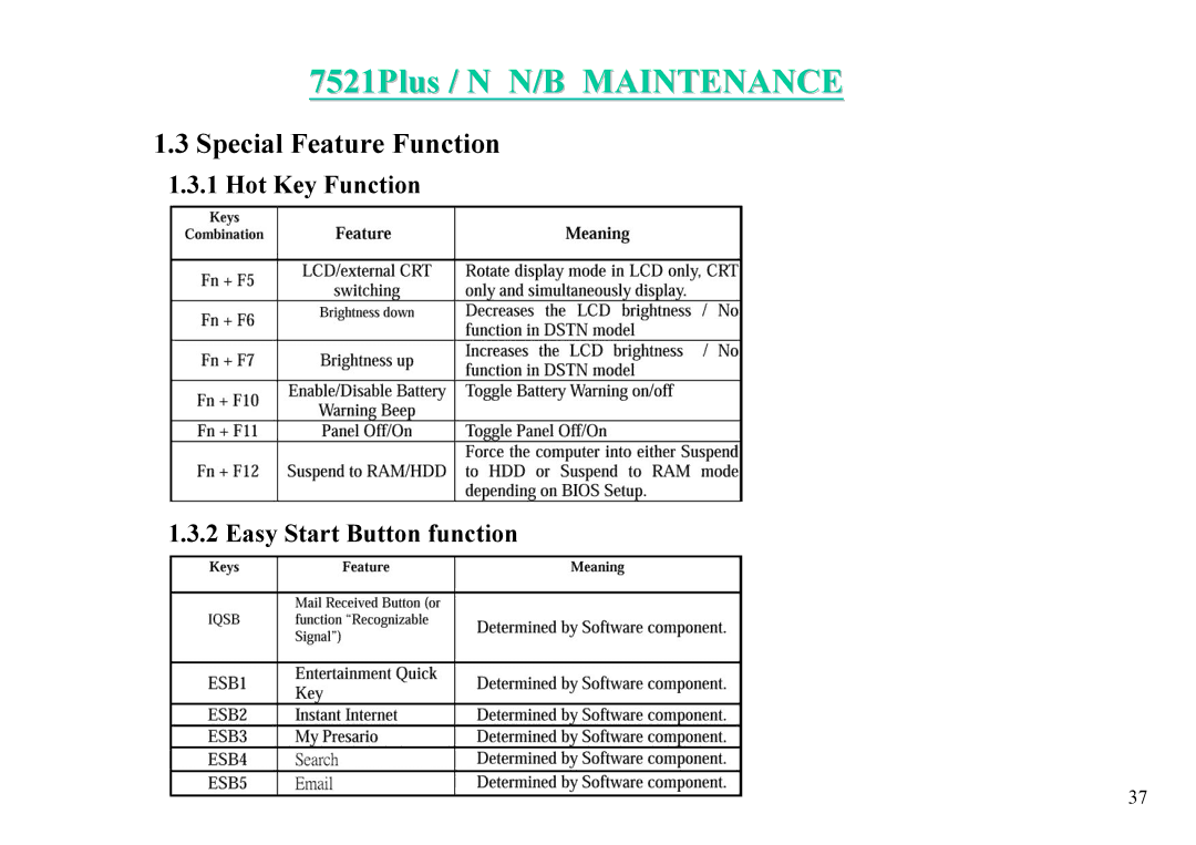
7521Plus / N N/B MAINTENANCE
1.3
Special Feature Function
1.3.1
Hot Key Function
1.3.2 Easy Start Button function
37
Page 37
Page 39
Page 38
Image 38
Page 37
Page 39
Contents
Plus/N
7521Plus / N N/B Maintenance
Plus/N Schematics
General Description
System Overview
Hardware System
Single Chipset
Synthesizer
4 SiS630S Slot 1/Socket 370 2D/3D Ultra-AGP
SiS630S Features
Integrated Dram Controller
Fast PCI IDE Master/Slave Controller
7521Plus / N N/B Maintenance
7521Plus / N N/B Maintenance
7521Plus / N N/B Maintenance
Integrated DMA Controller
Advanced PCI H/W Audio & Modem Advanced Power Management
Low Pin Count Interface
Integrated Keyboard Controller
Integrated Interrupt Controller
Three 8254 Compatible Programmable 16-bits counters
Integrated Real Time Clock RTC with 256B Cmos Sram
Universal Serial Bus Host Controller
Super IO NS PC 97338VJG
COM2
PC Card interface controller TI1225
Keyboard system H8 3434F universal keyboard controller
Memory
PWM timer 2 channels
Bit free-running timer
Bit timer 2 channels
Host interface HIF
Power-down modes
Interrupts
System Bios
System Bios and Software Features Overview
Bios Setup Feature Introduction
Concept
Acpi Power States
Summary of Global Power States
Sleeping State S3
Summary of Device Power Sates
System States Working S0
Hibernation S4
Soft Off State S5
Component Level Power Management Matrix
Mechanical Off
Standby
Power State 1.Full Power
Idle
Suspend
Off
Memory System
Interface
Audio System AC’97 Codec CS4299
Modem CD-ROM
IR Module HSDL-3600#007
7521Plus / N N/B Maintenance
SiS900 Features
Additional features
CH7005 Features
16 CH7005C Digital PC to TV Encoder
Hot Key Function Easy Start Button function
Flash ROM Bios
LED Indicators
SMM and System Bios
COM port assignment
Suspend to Dram
HDD & Video access
Battery Warning
Suspend to HDD
Battery Dead State
Battery Warning State
Battery Low State
Fan power on/off management
LCD Panel
Hard Disk Drive
Keyboard
Floppy Disk Drive
Touch Pad
24X CD-ROM Drive
DVD-ROM drive
CD-R/RW drive
IO port
LED Indicators
Cmos Battery
Serial Interface
Pcmcia Socket
FAN
Appendix 1 Gpio definitions
LCDSW4 LCDSW3 LCDSW2 LCDSW1
System View and Disassembly
Front View
Left-Side View
Right-Side View
Rear View
Bottom View
Top-Open View
System Disassembly
Battery Pack Disassembly
Reassembly
CPU Disassembly
7521Plus / N N/B Maintenance
Modem Card Disassembly
7521Plus / N N/B Maintenance
4 FDD/HDD Module Disassembly
7521Plus / N N/B Maintenance
CD-ROM Drive Disassembly
Hold the CD-ROM drive and slide it outward carefully. figure
Keyboard Disassembly
SO-DIMM Disassembly
LCD Assembly Disassembly
7521Plus / N N/B Maintenance
LCD Panel Disassembly
Inverter Board Disassembly
System Board Disassembly
7521Plus / N N/B Maintenance
Reassembly
7521Plus / N N/B Maintenance
Touchpad Disassembly
Definition & Location Of Connectors / Switches
Mother Board Switch Table
Mother Board-B
Daughter Board
Charger Board
Iqsb Board
Definition & Location Of Major Components
Main Board Side B
Bclk
ADS#
AERR#
BERR#
Clkref
BPRI#
BREQ0#
Cmosref
IERR#
GHI#
HIT#, HITM#
IGNNE#
PLL1, PLL2
RESET#
Picclk
PRDY#
Rttimpedp
RSP#
Rsvd
SLP#
VID40
HIT#
Cpuclk
HLOCK#
HITM#
SRAS#
Sdclk
WE#
SCAS#
PLOCK#
STOP#
DEVSEL#
INTAD#
VMA10
VMA11
Vgclk
Vbhclk
GPIO12
THERM#
Pmdat
Pmclk
Batok
ACRESET#
Auxok
OSC32KHI
GPIO0
CLK48M
PCIREQ3#
PCIGNT3#
Slots
System Bios
Pcmcia Cardbus
Codec
Maintenance Diagnostics
System Soft Bios
100
Diagnostic Tools
Circuit
Trouble Shooting
No Power
104
Symptom
PJ4
Next
Continue
There is no display on both LCD and monitor
System Clock Check
Apicclk
SIS
U24
112
U24 SIS 630S
114
U24
116
ISA
118
SIS
120
121
122
SIS
124
SIS
AC97SDIN0
AC97SYNC
127
128
129
130
131
SIS
133
Spare Parts LIST-1
Spare Parts LIST-2
Spare Parts LIST-3
Spare Parts LIST-4
Spare Parts LIST-5
Spare Parts LIST-6
Spare Parts LIST-7
Spare Parts LIST-8
Spare Parts LIST-9
Page
MTG14 MTG6
MTG8
GND
GND MTG9 MTG10
Picclk LINT1/NMI LINT0/INTR PICD1 PICD0 PLL2 PLL1
RESET#
TRDY#
PRDY# INIT#
Vssqa
Gtlrefa
Gtlrefb
Vssqb
INTB#
OVDD0 VSS0
INTA#
INTC#
TXIN0 VCC
Gout AAD0 AAD1 AAD2 AAD3 AAD4 AAD5
VBCAD/AREQ#
B4/ACBE2#
SPK LAD0
ACRESET#
VCC RESET# GND
PSON# LAD1
Xclk
VDD
Cvbs
Csync
Vddsdr FS1/PCICLK0
Vddref CPUCLK0
CPUCLK1 Vddsdr CPUCLK2
Vddsdr FS2/PCICLK1
PIN Sodimm Socket
CKE VDD1 VDD2
MAB#0
CLK VDD0
RAS VSS0
GND1
GND2
VSS
Sdat
RST#
GP17/INT GP26/INT
Primary IDE & FDD Connector
Idsel AD19
GND7 GND5
GND3 GND1
GND4 GND2
GND8 GND6
Bpcfg AUX/R
OUT0 IN0 OUT1 IN1 Nrerr Gndsd
AUX/L
FLT3D LINE/OUT/L
LED
PCIRST# SMEMR#
LFRAM#
Pciclk SMEMW#
Serirq REFRESH#
BOUT1/SOUT1
X1CLKIN
SIN1
AEN RTS1#/BADDR0
P40/TMCI0 MD1
RESET# GND
5VTAP Sense OUT ERR Shutdn GND
PB0/XDB0
GND VCC
CLK
CLR
OE#
VPP
CE#
VSS WE#
5VTAP Sense OUT
ERR Shutdn GND
Charger board connector
RS+ VCC
OUT GND0
Outputctrl DTC Feedback
PQ20A NDC7002NNA
12OUT
Reset
Shdn + Sync VL
BST3 BST5
SENSE1 SW1
RUN/SS1 Fltcpl
SENSE1+ TG1
VOSENSE1 BOOST1
Plus+5V+3V+12VS1.8V2.5V
FBS
VCC BST
Shdn Pgnd
Gnds
7521P HDD/FDD BD
QSB0# KI1 QSB1# KI2 QSB2# KI3 QSB3# KI4 QSB4# KI5 Swgnd KO0
R0A
Remove the reserved circuit R01 Relayout base on R0A
REV Description of Change ECR
75217521Plulus/Ns/N
Top
Page
Image
Contents