Edit NetCommand™, cont’d.
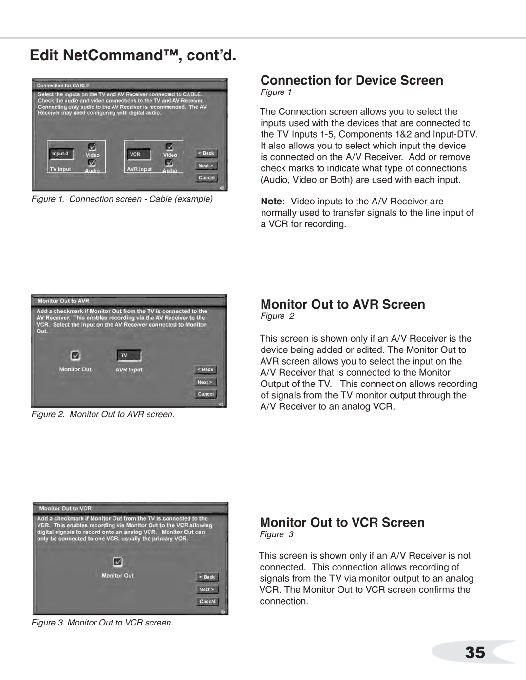
Figure 1. Connection screen - Cable (example)
Connection for Device Screen
Figure 1
The Connection screen allows you to select the inputs used with the devices that are connected to the TV Inputs
Note: Video inputs to the A/V Receiver are normally used to transfer signals to the line input of a VCR for recording.
Figure 2. Monitor Out to AVR screen.
Monitor Out to AVR Screen
Figure 2
This screen is shown only if an A/V Receiver is the device being added or edited. The Monitor Out to AVR screen allows you to select the input on the A/V Receiver that is connected to the Monitor Output of the TV. This connection allows recording of signals from the TV monitor output through the A/V Receiver to an analog VCR.
Monitor Out to VCR Screen
Figure 3
This screen is shown only if an A/V Receiver is not connected. This connection allows recording of signals from the TV via monitor output to an analog VCR. The Monitor Out to VCR screen confirms the connection.
Figure 3. Monitor Out to VCR screen.
35
