Monarch Printers
Canadian D.O.C. Warning
Trademarks
B L E O F C O N T E N T S
Getting Started
Page
Iii
Creating Graphics
Printing
Diagnostics and Errors
Vii
Viii
Page
Page
T T I N G S T a R T E D
O u t T h i s M a n u a l
F o r e Yo u B e g i n
E a t i n g a n M P C L I I F o r m a t P a c k e t
Type the following format header, in any text editor
Type the following constant text field
Type the following bar code field
Type the following text field
I l y S t a r t u p P r o c e d u r e s
Sample Batch Packet
A r t i n g w i t h a D e s i g n
6Getting Started
T e r m i n i n g F o r m a t C o n t e n t s
T e r m i n i n g t h e P r i n t a r e a
A w i n g R o u g h S k e t c h e s
I n g S u p p l y L a y o u t G r i d s
N s i d e r i n g F i e l d Ty p e s
Field Type Description Examples
I n g t h e F o r m a t Wo r k s h e e t
N s i d e r i n g F o n t s
T e r c h a n g i n g P a c k e t s
L l i n g i n t h e F o r m a t Wo r k s h e e t
12Getting Started
N F I G U R I N G T H E P R I N T E R
T t i n g C o m m u n i c a t i o n P a r a m e t e r s
O u t D I P S w i t c h e s
I n g P a r a l l e l C o m m u n i c a t i o n s
I n g a u t o b a u d
I n g M P C L I I C o n v e n t i o n s
C L I I P u n c t u a t i o n
A n d a r d S y n t a x G u i d e l i n e s
‘comment‘
I n g O n l i n e C o n f i g u r a t i o n P a c k e t s
N f i g u r a t i o n P a c k e t H e a d e r
Syntax
25,0,0,0 p
Header,ID#,action,device p
A,N,E p
U,N p
N f i g u r a t i o n S y n t a x G u i d e l i n e s
K i n g P r i n t a d j u s t m e n t s
F i n i n g t h e S y s t e m S e t u p P a c k e t
Syntax I,A,powupmode,language,sepon,slashzero, symbolset p
A1. a System Setup Packet
F i n i n g t h e S u p p l y S e t u p P a c k e t
12Configuring the Printer
B1. B Supply Setup Packet
Example I,B,0,0,1,10,50 p
14Configuring the Printer
Contrast,printadj,marginadjust
F i n i n g t h e P r i n t C o n t r o l P a c k e t
Speedadj,phwidth p
Cursym,secondary,decimals p
16Configuring the Printer
E1. E Control Characters Packet
Immediate command character optional
E2. ANSIcd
Start of header Left bracket
Parameter Comma Separator
S e t t i n g C o n t r o l C h a r a c t e r s
?E?~123~044~034~124~125~126~094 p
DTR default
Baud,wordlength,stopbits,parity
Flowcontrol p
For all printers
20Configuring the Printer
F i n i n g t h e B a c k f e e d C o n t r o l P a c k e t
Action,dispos,bkfddis p
2 p
Page
To reallocate in K Enter this amount
M1. M Memory Configuration Packet M2. buffer Buffer type
Buffer,device,buffersize p
Buffer Type 9403 9805 9820 9830/9835 9850 9840
24Configuring the Printer
M3. device Storage type
E c k i n g C u r r e n t B u f f e r S i z e s
9403 9805 9830/9835/9840 9850
26Configuring the Printer
O u t M e m o r y B u f f e r s
Linecount x 50/1024
Make copies of this page to use as a buffer worksheet
F f e r Wo r k s h e e t
F f e r a l l o c a t i o n C o n s i d e r a t i o n s
I n g I m m e d i a t e C o m m a n d s
A b l i n g I m m e d i a t e C o m m a n d s
N d i n g I m m e d i a t e C o m m a n d s
Command Parameter
DD or
DCd
ID or ICd
32Configuring the Printer
E a r i n g P a c k e t s f r o m M e m o r y
Action Enter C to clear the packet
SD or
I n g t h e F o n t P a c k e t
Clears Format #1 from volatile RAM
Font#,action,device p
Device Storage device. Options
Inter-Character Gap
34Configuring the Printer
Cell Height
Spacing
Monospaced 0 or proportional
Type
Bitmapped 0 or scalable
I n g t h e F l a s h U p l o a d P a c k e t
F,E,200,200,FMT1 p 5,A,F,E,400,200,FMT5 p
38Configuring the Printer
L o a d i n g F o r m a t H e a d e r I n f o r m a t i o n
A s h C o n s i d e r a t i o n s
Header,format#,action,device p
H,Z p
Selects all formats in memory and returns the following
Selects format1 and returns the following to the host
40Configuring the Printer
F I N I N G F I E L D S
2Defining Fields
F i n i n g t h e F o r m a t H e a d e r
Format Header begins a format file
F i n i n g Te x t F i e l d s
Field#,# of char,fix/var,row,column
Gap,font,hgt mag,wid mag,color,alignment
Char rot,field rot,sym set p
4Defining Fields
Printer Unit of Measure Row or Column or End Row End Column
Reduced
Bold
OCRA-like
CG Triumvirate
6Defining Fields
T12. alignment
Example T,2,10,V,250,50,0,1,1,1,B,C,0,0,0 p
F i n i n g B a r code F i e l d s
Each bar code field requires a separate definition
Bar Code Number of Characters Fixed or
Left/Center/Right-Justified Fields Balanced Fields
10Defining Fields
Printer Unit of Measure Row or Column or End Row End Column
12Defining Fields
B7. font Bar code. Options
Dots/mils Available
3 D P I B a r code D e n s i t i e s
Set
14Defining Fields
Alphanum
0 D P I B a r code D e n s i t i e s
16Defining Fields
Selector Width
Bar code Density
Row Height Aspect Data Appearance Char Set
18Defining Fields
Defining Fields
F i n i n g N o n P r i n t a b l e Te x t F i e l d s
F i n i n g C o n s t a n t Te x t F i e l d s
Field Data Field Type
Field#,# of char p
20 p
C2. row
22Defining Fields
C1. C
C8. color
C6. hgt mag
C7. wid mag
24Defining Fields
Example C,30,10,0,1,1,1,B,L,0,0,MADE in USA,0 p
F i n i n g L i n e F i e l d s
N e Ty p e s
26Defining Fields
Type,row,column,angle/end row,length
L5. angle/ If Using Segments end row
L6. length/ If Using Segments end col
Q2. row
F i n i n g B o x F i e l d s
Q1. Q
Example Q,240,30,270,150,3, p
F I N I N G F I E L D O P T I O N S
P l y i n g F i e l d O p t i o n s
M b i n i n g F i e l d O p t i o n s
S t r i c t i o n s
2Defining Field Options
%$ p
T i o n 1 F i x e d D a t a
Fixed char p
R1. R Option Header
T i o n 2 D a t a Ty p e R e s t r i c t i o n s
Charcode p
Code,chars p
T i o n 3 D a t a E n t r y Te m p l a t e s
Restricts the field data to letters only A-Z or a-z
T i o n 4 C o p y D a t a
R g i n g F i e l d s
Src fld,src start,# to copy,dest
Start,copy code p
Field Option Header
B F i e l d s
203 Non-printable 339 Text
Code p
T i o n 5 D e f i n e D a t a E n t r y S o u r c e s
Allows data to be entered from the keypad
20,Order Number p
T i o n 2 0 D e f i n e D a t a E n t r y P r o m p t s
20,prompt p
T i o n 3 0 P a d d i n g D a t a
M p l e U s e f o r P a d d i n g
Pads data with an X on the left side of the field
30,L/R,character p
R3. gen/ver Enter G to generate a check digit
T i o n 3 1 C a l c u l a t e C h e c k D i g i t
31,gen/ver,check digit # p
42,1 p
T i o n 4 2 P r i c e F i e l d
42,appearance code p
T i o n 5 0 B a r code D e n s i t y
50,narrow,wide,gap,narspace
Widespace p
50,4,8,4,4,8 p
Indicates Option
51,security,stand/default p
51,2,S p
16Defining Field Options
52,row/column,dimension p
T i o n 5 2 P D F 4 1 7 W i d t h / L e n g t h
60,I/D,amount,l pos,r pos p
60,I,5,1,6 p
T i o n 6 1 R e i m a g e F i e l d
Fldlength,D/P,weights p
I n g C h e c k D i g i t s
Selector,action,device,modulus
Check Digit Header
20Defining Field Options
M o f P r o d u c t s C a l c u l a t i o n
1,2,3,4
M o f D i g i t s C a l c u l a t i o n
20 + 2 + 6 + 6 + 16 + 5 + 4 + 3 + 36 =
+ 0 + 2 + 6 + 6 + 1 + 6 + 5 + 4 + 3 + 3 + 6 =
22Defining Field Options
E a T I N G G R a P H I C S
E r v i e w o f C o m p l i a n c e L a b e l s
E r v i e w o f B i t m a p p e d I m a g e s
T e r m i n i n g a M e t h o d
Hex Method
Run Length
E c i a l C o n s i d e r a t i o n s
S i g n i n g C o m p l i a n c e L a b e l s
S i g n i n g B i t m a p p e d I m a g e s
I n g t h e H e x M e t h o d
Exceeds
Inches
Limit
Assign 1 to every black square and 0 to every white square
6Creating Graphics
I n g t h e R u n L e n g t h E n c o d i n g M e t h o d
Row 1, position 50 26 on
T e r m i n i n g H o w t o S t o r e t h e I m a g e
I n g F l a s h
I n g Te m p o r a r y S t o r a g e
I n g N o n v o l a t i l e R a M
I n g Vo l a t i l e R a M
T h i n t h e G r a p h i c P a c k e t H e a d e r
E a t i n g a G r a p h i c P a c k e t
S i t i o n i n g t h e G r a p h i c I m a g e
T h i n t h e F i e l d
G1. G Graphic Header
F i n i n g t h e G r a p h i c H e a d e r
T h i n a F o r m a t
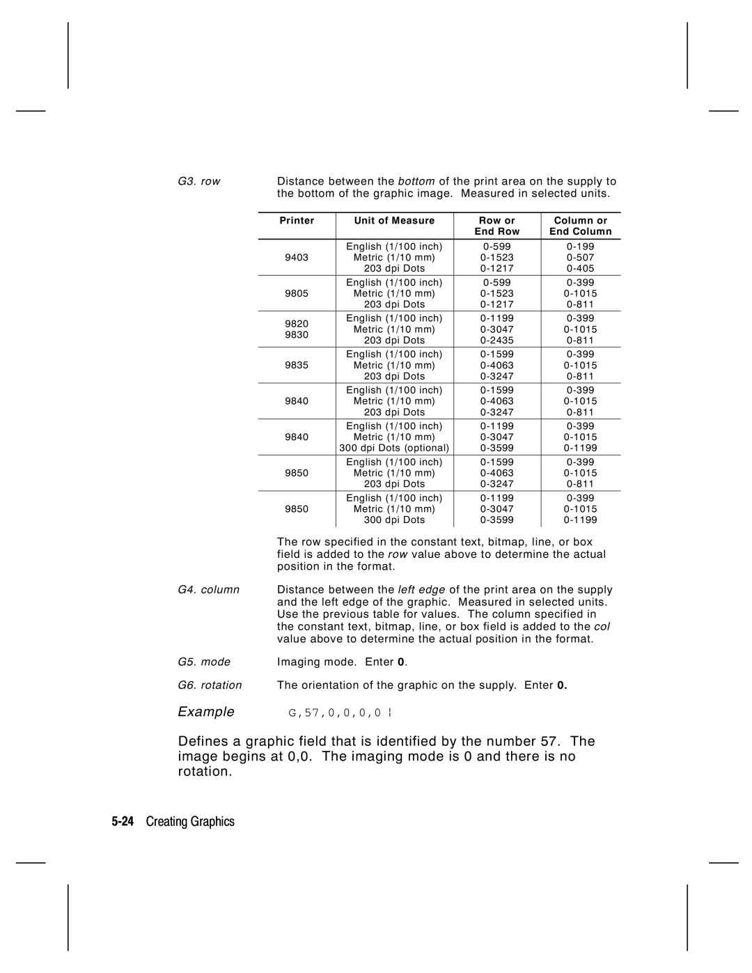
G6. row
14Creating Graphics
G5. units
99,A,R,G,0,0,0,99Wire p
E a t i n g B i t m a p F i e l d s
Row,column,algorithm,data p
B1. B Bitmap Field
B2. row
B3. column
B4. algorithm
B5. data
E a t i n g N e x t B i t m a p F i e l d s
Adjdir,adjamt,algorithm,data p
E a t i n g D u p l i c a t e F i e l d s
Adjdir,adjamt,count p
117,24,H,03FFFFFFFFFFFFFFFFFFFC p
1,2 p
M p l e C o m p l i a n c e G r a p h i c P a c k e t
Sample compliance graphic packet is shown below
M p l e H e x G r a p h i c P a c k e t
20Creating Graphics
M p l e R u n L e n g t h G r a p h i c P a c k e t
22Creating Graphics
GraphID,row,col,mode,rotation p
A c i n g t h e G r a p h i c i n a F o r m a t
F i n i n g t h e G r a p h i c F i e l d
G5. mode
G3. row
G4. column
G6. rotation
M p l e C o m p l i a n c e L a b e l
M p l e B i t m a p G r a p h i c I m a g e
26Creating Graphics
I N T I N G
Page
F i n i n g t h e B a t c h H e a d e r
Batch header
Batch control
Batch data
E1. E Batch Control Field
F i n i n g t h e B a t c h C o n t r o l F i e l d
4Printing
1,4,2,1,4 p
F i n i n g B a t c h D a t a F i e l d s
E c i a l P r i n t i n g C o n s i d e r a t i o n s
R g e d o r S u b F i e l d s
C r e m e n t i n g F i e l d s
Sample Batch Data with Special Characters
8Printing
W n l o a d i n g M e t h o d s
Q u e n t i a l M e t h o d
T c h M e t h o d
T c h Q u a n t i t y Z e r o M e t h o d
D i f y i n g F o r m a t s
T i o n a l E n t r y M e t h o d
A T U S P O L L I N G
Indicates the printer is offline 2Status Polling
Q u i r y R e q u e s t E N Q
Q u i r y R e s p o n s e
Page
Char Const Comp Corr Online Busy Active
Failure Error Data
Q R e f e r e n c e Ta b l e B y t e #
Q R e f e r e n c e Ta b l e B y t e # 2 c o n t i n u e d
Battery Error Fault Dispense Label
Char Const Low Format Waiting Ribbon Stock Online
Q R e f e r e n c e Ta b l e B y t e # 3 c o n t i n u e d
B R e q u e s t
Field Type Valid Options Description Identifier
B R e s p o n s e
Status1,Status2,FMT-1,BCH-2
Status2
Packet Type
Error Number
Field Number
Parameter
FMT-1/BCH-2
25,FMT-3,Bch-2
Following syntax is the response for a Job 4 request
Printed,total,FMT-1,BCH-2
Number Meaning
14Status Polling
A G N O S T I C S a N D Error S
I n t i n g a Te s t L a b e l
I n g t h e 9 4 0 3 o r 9 8 5 0 P r i n t e r
I n g t h e 9 8 0 5 P r i n t e r
Yo u R e c e i v e a n Error M e s s a g e
Installed Options Description
L l i n g Te c h n i c a l S u p p o r t
S e t t i n g P r i n t e r s
D i t i o n a l D i a g n o s t i c s I n f o r m a t i o n
A d i n g a n Error L a b e l
T a Error s
Error Description Code
Page
Page
Page
Page
Page
Page
Page
M m u n i c a t i o n F a i l u r e s
Page
T a F o r m a t t i n g F a i l u r e s
Page
Page
C h i n e Fault s
Page
Page
RAM check failed on power up. Reset
ROM Sum Failure 24Diagnostics and Errors
Printer Description Display
ROM checksum test failed
Timer test failed
Timer Failure
Not enough RAM for system. Reset your
Low System RAM Setup options. Transmit your packets Again
26Diagnostics and Errors
I N T E R O P T I M I Z AT I O N
J u s t i n g t h e P r i n t Q u a l i t y
Dark
Light
D u c i n g I m a g i n g T i m e
4Printer Optimization
N e r a l F o r m a t T i p s a n d H i n t s
C r e a s i n g T h r o u g h p u t
T h F o r m a t s
T h P a c k e t s
T h F i e l d s
You can group fields with similar parameters. For example
T h B a r codes
M P L E SA
M p l e U P C a F o r m a t P a c k e t
2Samples
Mode Description
M p l e M a x i code P a c k e t s
D e 0 O b s o l e t e S a m p l e
4Samples
D e 2 S a m p l e
Samples A-5
D e 3 S a m p l e
6Samples
C t a n g u l a r D a t a M a t r i x P a c k e t
M p l e D a t a M a t r i x P a c k e t s
U a r e D a t a M a t r i x P a c k e t
M p l e C o m p l i a n c e P a c k e t
8Samples
Samples A-9
10Samples
M p l e F o r m a t P a c k e t
Samples A-11
Sample Zero Batch Packet
12Samples
M p l e D a t a E n t r y F o r m a t P a c k e t
14Samples
N T S
2Fonts
Standard Font
Bold Font
These samples were printed using Code
CG Triumvirate Bold Font
CG Triumvirate Font 9pt
Fonts B-3
4Fonts
T m a p F o n t I n f o r m a t i o n
F TA F o n t 7 2 a n d F o n t 7 3 C h a r a c t e r s
N o s p a c e d F o n t M a g n i f i c a t i o n
I n g 2 0 3 D P
I n g 3 0 0 D P
Width Mag Standard Reduced Bold
Fonts B-7
8Fonts
Fonts B-9
O p o r t i o n a l F o n t M a g n i f i c a t i o n
Tr i u m v i r a t e B o l d 9 p t 0 3 D P
I g h t M a g n i f i c a t i o n 2 0 3 D P
Fonts
Fonts B-11
Tr i u m v i r a t e B o l d 9 p t 0 0 D P
I g h t M a g n i f i c a t i o n 3 0 0 D P
I g h t M a g i n f i c a t i o n 2 0 3 D P
Tr i u m v i r a t e 6 p t 0 0 D P
Fonts B-13
Tr i u m v i r a t e 7 p t 0 3 D P
Tr i u m v i r a t e 7 p t 0 0 D P
Tr i u m v i r a t e 9 p t 0 3 D P
Fonts B-15
Tr i u m v i r a t e 9 p t 0 0 D P
Tr i u m v i r a t e 1 1 p t 0 3 D P
Tr i u m v i r a t e 1 1 p t 0 0 D P
Tr i u m v i r a t e 1 5 p t 0 3 D P
Fonts B-17
Tr i u m v i r a t e 1 5 p t 0 0 D P
A l a b l e / Tr u e Ty p e F o n t I n f o r m a t i o n
R m a t C o n s i d e r a t i o n s
O u t t h e S c a l a b l e F o n t 5
Font Supported Code Pages
W n l o a d i n g Tr u e Ty p e F o n t s 9 8 4 0 / 9 8 5
I n g a s i a n 2 B y t e Tr u e Ty p e F o n t s 9 8 5
C e n s i n g Yo u r F o n t s
Fonts B-23
I n g F o n t N u m b e r s i n F o r m a t s
100
500
1000
Example
Fonts
P p o r t e d S y m b o l S e t s a n d code P a g e s
L e c t i n g t h e I n t e r n a l S y m b o l S e t
Use Ansi when you want to use proportionally spaced fonts
I n g code 1 2 8 F u n c t i o n codes
T e r i n g E x t e n d e d C h a r a c t e r s
L e c t i n g t h e a N S I S y m b o l S e t
Symbol Sets/Code Pages C-3
T e r n a l S y m b o l S e t
4Symbol Sets/Code Pages
S I S y m b o l S e t L d C h a r a c t e r S e t
Symbol Sets/Code Pages C-5
6Symbol Sets/Code Pages
Symbol Sets/Code Pages C-7
Code P a g e 8 5 0 L a t i n Code P a g e 8 5 2 L a t i n
8Symbol Sets/Code Pages
Symbol Sets/Code Pages C-9
10Symbol Sets/Code Pages
Symbol Sets/Code Pages C-11
12Symbol Sets/Code Pages
Symbol Sets/Code Pages C-13
14Symbol Sets/Code Pages
Char Hex Decimal
Symbol Sets/Code Pages C-15
16Symbol Sets/Code Pages
Symbol Sets/Code Pages C-17
N a r y t o H e x C o n v e r s i o n C h a r t
18Symbol Sets/Code Pages
Symbol Sets/Code Pages C-19
20Symbol Sets/Code Pages
Symbol Sets/Code Pages C-21
T t o R u n L e n g t h E n c o d i n g C h a r t
B l a c k D o t s
F W h i t e D o t s
22Symbol Sets/Code Pages
R M AT D E S I G N T O O L S
L i n e C o n f i g u r a t i o n Wo r k s h e e t
Control Characters
T c h Wo r k s h e e t
Batch Control Continuation
E c k D i g i t Wo r k s h e e t
Supply Layout Inches
203
200 190 180 170 160 150 140 130 120 110 100
192 288 384 480 576 672 768 806
102 203 305 406 508 609 711 812 853
Supply Layout dpi 300
102 203 305 406 508 609 711 812
Format
Sample
Printer Differences E-1
Feature 9403 9805 9820 9830 9835 9840 9850 9446
I n t e r C o m p a r i s o n
2Printer Differences
Feature 9403 9805 9820 9830 9835 9840 9850 9446
Default configuration packet settings are
I n t e r C o n f i g u r a t i o n I n f o r m a t i o n
A t u s P o l l i n g I n f o r m a t i o n
4Printer Differences
Monarch p
1,4,2 p Batch Header
N,1
Batch Packet
Monospaced Fonts
Non-volatile RAM
Option
6,1,3,1 p
D E
Index
Packet control characters Security level of P D F417
Guidelines Header
Online configuration w orksheet Orksheet overview
Feed m ode selection Field
IM D
Argin adjustm ent selection 2
Data entry prom pts Data entry sources
Parity selection
Batch packet Calculate check digit option
Text field Zero batch packet Scalable font
Run length conversion Technical support Test label