User’s Guide
Page
Installation Considerations
Standards Compliance
Limitation of Liability
Page
Contents
Features and Applications 125
Using ION Software
Standard Meter Security
Environmental Conditions Unit Dimensions
Hardware Reference 159
Telnet and Hyperterminal
Appendix a Technical Notes 183
Introduction
Firmware Revision History Using this Guide
ION 7500 and ION 7600 Meters
Introduction
Data Display and Analysis Tools
ION meter in an Enterprise Energy Management System
XML Compatibility
WebMeter Embedded Web Server Feature
MeterM@il Internal E-Mail Server Feature
Front Panel
Digital Inputs
ION Setup Software
Communications Protocols
Digital and Analog I/O Options
Analog Inputs and Analog Outputs
Meter is Factory-Configured and Ready to Operate
V203 Apr
Firmware Revision History
Before You Can Use this Guide
Using this Guide
Getting More Information
Application Notes
ION Enterprise Administrator Guide
Online ION Enterprise Help
Technical Notes
Displaying Data with the Front Panel
Configuring the Meter with the Front Panel
Softkeys
Using the Front Panel Buttons to Display Data
Displaying Data with the Front Panel
Navigation Buttons
Status Bar
Display Screen Types
Front Panel LEDs
Backlight Operation and Display Contrast
Histogram Displays
Phasor Diagram Displays
Event Log Displays
Nameplate Displays
Trend Displays
Trend Bar Graph Displays
Screens Shown in Display Cycle
Default Front Panel Display Screens
Additional Data Display Screens
Setpoint Setpoint Status
Phasors Phasors
Name Plt Name Plate Info
Events Event Log
EN50160 Data and Statistics Displays ION 7600 only
Trending Display Screens in the ION
Front Panel’s Setup Menu
Configuring the Meter with the Front Panel
Confirming Configuration Changes
Using the Front Panel Buttons for Configuration
Passwords
Setup Mode Timeout
Sub-Menu Register Default Description
Basic Setup Menu
Sliding Window sub-menu contains the following settings
Main Setup Menu
Demand Setup Menu
Sliding Window Demand Rolling Block Settings
Demand Options
Thermal Demand Settings
Thermal sub-menu contains the following settings
Demand Options sub-menu contains the following setting
Setting Description Default
Network Setup
Following settings can be configured in this option
Configuring Network Settings with BootP
89.123.40
Configuring Network Settings Through the Front Panel
COM Port Setting Options Default
Serial Communications Setup
Internal Modem Setup
Change Criteria
PQ Power Quality Setup
Sag Limit
Swell Limit
Numeric Format
Format Setup Menu
Numeric Format sub-menu contains the following settings
General Format sub-menu contains the following settings
Clock Setup
Display Setup Menu
Time Setup Menu
Use this item to set the meter’s display to local time
Set Meter Time
Peak dmd rset
Meter Resets
Factory Resets
This sub-menu contains the following default resets
EN50160 Reset ION 7600 only
Security Setup
User Resets
Web Config
Password
Enabled
Maximum Module
Creating a Front Panel Reset
Custom Front Panel Displays
External Pulse Module #6
To access the External Pulse modules #4 or #6 using Designer
Using The Front Panel
Default Meter Functionality
Setup Function Default Register
Default Meter Functionality
Basic Setup
Communications modules control the following channels
Communications Setup
Module Name Settings
Communications Port Setup Register Function Default
Communications Protocols
Modem Initialization String
Log name Depth Interval
Data Logging Setup
Default Logging Capacity
Changing the Log Depths
Parameter Description
Default Logging Configuration
Changing the Frequency of Logging
Revenue Log
Harmonics Logging
Historic Data Logging
Loss Log
ION Enterprise Reporting
Time-of-Use Logging
EN50160 Compliance Logging ION 7600 only
Sag/Swell and Transient Logging
Meter logs the following ION output register values
Calibration Pulser Module Settings
Energy Pulsing Setup
Pulser Module Settings
Setup Register Function Default
Power Quality Configuration
Sag/Swell Module Settings
EN50160 Settings ION 7600 only
Transient Module Settings ION 7600 only
To a varying value
Setpoint Configuration
Fine Tuning Over Condition Monitoring
Relative Setpoint Module Settings
Number of seconds since 000000 UTC on Jan 1
Meter Clock Configuration
On using the meter’s time synchronization functions
Display Module Settings
Display Setup
Display Options Module Settings
Scroll Module Settings
Changing the Parameters that are Displayed
Demand Setup
Sliding Window Demand Module Settings
Thermal Demand Module Settings
Time Of Use Module Settings
Time of Use Configuration
Seasonal Settings
Manager in Designer from the Options menu
Setup Register Function
Creating a New Time Of Use Schedule
Factory Information
How to TAG Your Meter
Factory Module Settings
Setup Register Description
Third Party Protocols
Communications Protocol Configuration
Changing the Modbus Configuration
Using the Modbus RTU Protocol
Factory Modbus Configuration
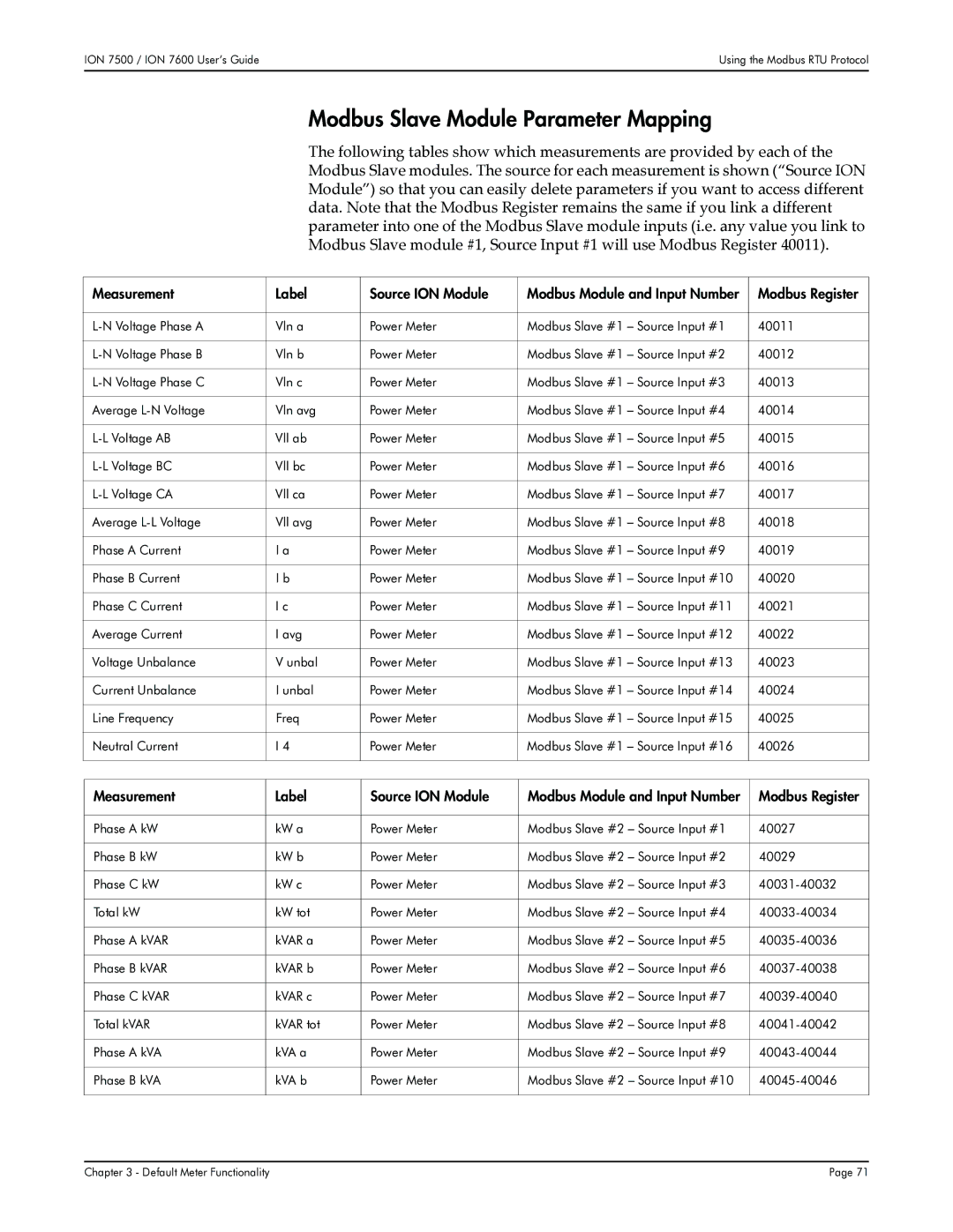
Modbus Slave Module Settings
Modbus Slave Module Parameter Mapping
Default Meter Functionality
Refer to Appendix a for more
Default Meter Functionality
Default Meter Functionality
Default Meter Functionality
Default Meter Functionality
Importing Data using Modbus RTU
Modbus TCP Communications
Using the Modbus/TCP Protocol
Vln a
Using the DNP 3.00 Protocol
Factory DNP 3.00 Configuration
ION 7500 / ION 7600 User’s GuideUsing the DNP 3.00 Protocol
Changing the DNP Configuration
DNP Slave Export Module Settings
Setup Register Setting Function
DNP Options Module Settings
Importing Data using DNP
Click OK on the confirmation dialog box
Restoring the Factory Configuration
To restore the factory configuration
Default Meter Functionality
Using ION Software
Software Security
ION Enterprise Software
Servers
ION Enterprise ION Management Console
Connection Schedules
Sites
Devices
Dialout Modems
Adding a new Server, Site, Device or Dialout Modem
Configuring Communications
Configuring Communications ION 7500 / ION 7600 User’s Guide
Displaying Data with Vista
Generating a network diagram in Vista
ION Enterprise Vista
Displaying Data if the Software is Not Fully Configured
Vista Diagram Elements
Volts/Amps
Historic Data Logging Enable
Power Quality
Summary of Data Provided in Vista
EN50160 Measurements ION 7600 only
Instantaneous Power
Harmonics Trending
Long-Term Harmonics Min/Max Measurements
Loss Compensation
Setup and Controls
Energy & Demand by Quadrant
Demand Max and Demand Min
Over kW Sliding Window Demand Monitoring
Per Phase Over Current Monitoring
Setpoints
Inputs
Voltage Unbalance Monitoring
Time-of-Use Tables
TOU- Peak Demand Details
Analog Inputs/Outputs
Revenue Test Mode
Revenue Test Mode Values
Customizing the Vista Interface
Custom Appearance of a User Diagram
Diagram Objects in a User Diagram
Basics of ION Architecture
ION Enterprise Designer
Module Linking Restrictions
ION Modules
‘NOT AVAILABLE’ Value
ION Registers
Sequence of ION Module Execution
Persistent Modules
ION Configuration Changes and Module Security
Core Modules
Fixed Module Links
Designer’s Main Configuration Screen
To view real-time data of output registers
Changing Setup Registers with Designer
Viewing Real-time Data in Designer
To configure ION module setup registers with Designer
Customizing Frameworks in Designer
Follow these steps to create an ION module in the meter
Creating New Modules
Deleting Modules
Linking Modules
Follow the steps below to link modules on the meter
Replacing a Link
Editing Existing Frameworks
Checking an Output Register’s Owner
Deleting the Link at a Module’s Input
ION Enterprise Reporter
Pre-configured Reports
EN50160
Power Quality
Energy and Demand
Load Profile
Generating the Report
Report Creation and Generation
Creating a Report
Changing Which Days are Holidays
Creating a Time of Use Schedule
Adding a Shoulder Period
ION Setup Software
Adding a Site, Group or Meter
Sites, Groups, and Meters
Configuring Communications ION 7500 / ION 7600 User’s Guide
Changing a setup register
Basic Meter Configuration
Displaying real-time data
Displaying Data with ION Setup
Displaying diagnostics data
Using ION Software
Time Synchronization Meter Security
Digital and Analog I/O
COM Port Available Connections Standard/Option
Communications
External Modem Connections
RS-232 Connections
Computer Connections
Meter Connections
Loop Topology
General Bus Wiring Considerations
RS-485 Connections
Straight-Line Topology
RS-485 Connection Methods to Avoid
Ethernet Connections
Configuring the Ethernet Module in Designer
Meter Setup for Ethernet Communications
Configuring the Ethernet Module through the Front Panel
Configuring the Ethernet Module via Designer
EtherGate Protocol
Internal Modem Connections
ModemInit Setup Register
Modem Initialization Strings
Problem Add to Modem Initialization String
Configuring the Comm 3 Communications Module in Designer
Configuring the Comm 3 Module through the Front Panel
Configuring the Comm 3 Module via Designer
Workstation with ION Enterprise and modem
ModemGate Protocol
Infrared Port Connections
WebMeter and MeterMail
ION WebMeter Feature
ION MeterM@il Feature
Internet Connectivity
Telnet and Hyperterminal
WebReach
Specifying a Port in an ION Module
Digital and Analog I/O
Optional Input Port Names Description
Standard Output Port Names Description
Optional Output Port Names Description
Standard Input Port Names Description
Output Modules
Using the Onboard Digital Outputs
Calibration Pulsing Relay DO4
KWh Pulse -LED
Alarm LED
Energy Pulsing with LEDs
Settings in the Digital Input modules are as follows
Using the Onboard Digital Inputs
Analog Outputs
Analog Inputs
Enabling or Customizing Time Synchronization
Time Synchronization
Your revenue meter can be protected by anti-tamper sealing
Entering the Password through the Front Panel
Meter Security
Standard Meter Security
Disabling and enabling password security
Changing the Meter Password
Changing Waveform Recording
Data and Event Logging
Data Logging
Changing the Parameters that are Logged
Event Group Description Priority Number
Event Logging
ION Event Priority Groups
External ION Events
Logging and Recording Capacity
Log Depth Interval
Logging Configurations for ION 7500 Revenue Applications
Alerting
Alerting ION Software via the Alarm Server
Server or LAN
Configuring the Alarm Server
Alarm Server Command Line Arguments
Remote Site Event Notification
Alerting via an Alphanumeric Pager
Alerting via a Numeric Pager
Alerting via Email
Calculating Power Availability Number of Nines
Hardware Reference
+ 30 V max
Standard Model
Rear View of Meter
+ N
Environmental Condition Acceptable Range
General Specifications
Environmental Conditions
Basic Model Side View
Unit Dimensions
Basic Model Rear View
Basic Model Front View
RJ11
Communications Specifications
RS-232 Connections
COM1 Port
LEDs
Terminal connections on the meter are marked as follows
Specifications are as follows
RS-485 Connections
Connections
RJ11
COM2 Port
COM3 Port
Internal Modem
Optical Infrared
Specifications for the optical port are as follows
Specifications for the Ethernet ports are as follows
Ethernet Port
Protocol TCP/IP Port
IP Service Ports
AI1
Specifications
Internal Excitation Additional External Excitation Optional
Specification Standard I/0
Mechanical Relay Outputs
RX1 RX2 RX2 RX3
Operational Block Diagram
Solid-State Relay Outputs
Wh pulsing
Analog Outputs
Max Relays
I/O expansion card can be ordered with 4 analog outputs
Analog Inputs
Specification MA Analog Inputs
Potential Transformers PTs
Electrical Specifications
Power Supply
Voltage Inputs
Current Inputs
Specification 5A Option 1A Option
Terminal Cover
Installation Instructions
Installation Diagram
Retrofit Options
Removing the Existing Communications Card
Installing the New Card
Communications Card
Final Steps
Installing the I/O Card
Expansion Card
ION 7500 / ION 7600 User’s Guide Expansion Card
Tran Model Front View
Tran Model
Environmental Conditions
Tran Model Side View
Unit Dimensions ION 7500 / ION 7600 User’s Guide
Technical Notes
ION 7500 / ION 7600 User’s Guide
Calibration Menu and the KCTSTP/KCTRD Commands
Basic Setup is not required
Basic Setup is required
To perform current probe basic setup
Current Probe Basic Setup
Telnet and HyperTerminal Access
To perform current probe basic setup
Description
Calibration Menu and the KCTSTP/KCTRD Commands
Description of Kctstp and Kctrd Calibration Commands
Calibration Menu and Help
PH C
Example
None
Read all current probe setup registers
Screen Messages Adding New Trend Display Modules
Introduction ION Modules in the Display Framework
Display Modules Display Options Module Scroll Modules
ION Modules in the Display Framework
Introduction
Screen Types Max. # Display Description Source Inputs
Display Modules
Display Modules for ION 8000 Series, ION ION 7600 Meters
Screen Types
Changing ION 7300 Series Display Module Default Settings
Display Modules for ION 7300 Series Meters
Scroll Modules
Display Options Module
Module Behavior in the ION 7300 Series Meters
Display Framework Overview
Module Behavior in ION 8000 Series and ION ION 7600 Meters
For the ION 7300 Series
Changing Default Display Frameworks
Making a Framework Backup
For the ION 8000 Series and ION 7500 / ION 7600 meters
To add a new display screen in Designer
Removing a Display Screen
Adding a New Display Screen
To remove a data display screen
Changing displayed parameters in an existing screen
Changing Displayed Parameters using the Meter’s Front Panel
Changing Displayed Parameters in an Existing Screen
Before changing displayed parameters in an existing screen
Bar Graph Input Function Attributes
Creating Custom Trend Bar Graphs ION 7500 / ION 7600 only
Power Meter Module
Selecting and navigating the Trend Display screen
Trend Display Screen
Trending Data Log Screen
Use the ESC key to exit the Trend Display
To change the logging interval for Trend Display data
Screen Message Description
Screen Messages
Adding New Trend Display Modules
To create a Disk Simulator screen
Disk Simulator ION 8000 Series
Customized Display Framework
To configure your custom display framework
Displaying Data from Other Meters
Display
Custom Front Panel Displays Technical Note
Analog Input Module
Digital Input Module
Digital and Analog I/O Technical Note
Meter Digital Analog Modbus Inputs Outputs Master ION
Solutions
Onboard I/O for ION Meters
External I/O with Grayhill Products
Expander for ION 8000 Series Meters
Expansion Boards for the ION
Grayhill analog hardware module restrictions-power supplies
Digital Output Boards for ION 7300 Series Meters
Expansion Boards for Meters with Modbus Master Capability
Description Maximum draw per channel for I/O
Power Requirements
Switch Setting Parameters
Communications Considerations
Configuring Digital and Analog I/O
Specifying a Debounce Time
Configuring Digital Input
Digital Input Module Setup Registers
Digital Input Module
Detailed Operation Pulse or KYZ Input Mode
Digital Output Module
Configuring Digital Output
Digital Output Module Setup Registers
Detailed Operation
Calibration Pulser Module Setup Registers
Calibration Pulser Module
Pulse Width
Pulse mode KYZ mode
Detailed Module Operation
Normal State
Overload State
Pulse mode
Maximum State
Pulser Module
Pulser Module Setup Registers
Analog Input Option Input Impedance Max Common Mode Voltage
Configuring Analog Input
Analog Input Module Setup Registers
Connecting Auxiliary Analog Inputs ION 7700 Meters
Zero Scale
Analog Output Option Maximum Load
Configuring Analog Output
Analog Output Module Setup Registers
Analog Output Module
Setting Analog Zero and Full Scale Values
To 20 mA
Considerations when scaling
20 to
20 mA
1500 W 0mA 1000 W 4mA 20mA
Assigning a port to a module
Configuring ION Modules for Digital and Analog I/O
Configuring modules for digital or analog I/O
Making a port available
Energy Pulsing from ION Meters
Email Alerts Email Data Logs
Setting Up the Network for the MeterM@il Feature
Configuring the Meter for MeterM@il Technology
Introduction Viewing the MeterM@il Message
Recipient of the MeterM@il Message
Network Administrator
Setting Up the Network for the MeterM@il Feature
ION Software Administrator
Here is an example of an email alert
Viewing the MeterM@il Message
Email Alerts
Email Data Logs
XML Attachment
BootP Server
Automatically Configuring Meter Network Settings
Setting Up the Network for the MeterM@il Feature
Smtp Connection Timeout
Optional
Click Send and save
Configuring the Meter for MeterM@il Technology
‘Setting Up the Meter for the Smtp Server
Setting Up the Meter for your Smtp Server
Setting up the meter to send alerts
Configuring the MeterM@il Feature to Send Alerts
Configuring the MeterM@il Feature to Send Data Logs
Configuring the meter to send data logs
Additional ION Module Configurations
MeterM@il Internal Email Server Feature Technical Note
Factory Module
MeterM@il Technology in a Modbus Network
MeterM@il Internal Email Server Feature Technical Note
ION Meter Security
Overview of Security
Standard Advanced
Overview of Security
ION Software Security ION Meter Security
Icon Descriptions
Supervisor Operator Controller User View Only
Security Access Levels
ION Enterprise Software Security
Creating or modifying ION Enterprise user accounts
Entering the software user name and password
Creating or modifying ION Setup user accounts
ION Setup Software Security
ION Setup Software Security ION 7500 / ION 7600 User’s Guide
ION Meter Security
Meter Password
Configuring standard meter security in Designer
Configuring standard meter security in ION Setup
Advanced Meter Security ION 8000 Series
Configuring advanced security using ION Enterprise
Entering an advanced security user name and password
Enter the appropriate password and click OK
Configuring advanced users with ION Setup
Configuring advanced security using ION Setup
ION 7500 / ION 7600 User’s Guide
Service Function
Device Security Access for ION Services
Launch ION Setup and connect to the appropriate meter
Hardware Lock Security
Additional Revenue Metering Security
Anti-Tamper Seals
Hardware Framework
Default Web Pages Custom Web Pages
Using the Setup Page Setup Errors
Web Browser User
Viewing WebMeter Data on the Internet Configuring your Meter
Viewing WebMeter Data on the Internet
Default Web Pages
Viewing default web pages
Creating custom web pages
Custom Web Pages
Viewing custom web pages
For example http//10.1.50.42/webpage1.html
Configuring your meter with the Setup
Configuring your Meter
Using the Setup
Undo Changes
Setup Errors
Automatic Configuration via a BootP Server
Configuring Meter Network Settings
Smtp Mail Server Address mandatory for MeterM@il
WebMeter Network
WebMeter Network ION 7500 / ION 7600 User’s Guide
Enabling/disabling web browser configuration of the meter
Enabling/Disabling Meter Web Browser Configuration
Enabling/disabling web server functionality of the meter
Enabling/Disabling Meter Web Server Functionality
Framework
Using WebMeter in a Modbus Network
Below is a typical application of the WebMeter feature
Hardware
Web Page Module
Factory Module
Modbus Import Module
Cellular Phone Compatibility 289
AT Commands for the Conexant Modem
Conexant Modems in ION Meters
ION meter
ION Meter Internal Modem Types
International support
Multi-Tech Internal Modem Settings
AT Commands for the Multi-Tech Modem
Multi-Tech Modems in ION Meters
Configures the modem for pulse non-touch-tone
Registers
Register Unit Range Default Description
Configuration settings for certain types of connections
Conexant Modems in ION Meters
AT Commands for the Conexant Modem
Command Group Members Description
Mod Modulation Possible Rates bps
AT+MS Commands Select Modulation
Cellular Phone Compatibility
Changing the Internal Modem Settings
Changing the Local Modem Settings
Description If rate drops to 1200, use Bell protocol
AT command S10=100
AT command B1
Description Increases disconnect time on loss of carrier
Terminology
Resetting and Pausing Power Availability
Introduction Availability on the Meter Front Panel
Detailed Behavior
Firmware
Availability Features Comments Versions
Availability Framework Release History
Assumptions
Availability on the Meter Front Panel
Sample Availability Framework Behaviors
Meter
Sag/Swell Module Configuration
Power Operating Range Supply 36S 35S Phase
Blade Powered
Resetting Availability with ION Setup Software
Resetting and Pausing Power Availability
Resetting Availability with Vista
ION 7500 / ION 7600 meters only
Resetting Availability through the Meter Front Panel
Pausing Availability
Detailed Behavior
Terminology
Detailed Behavior ION 7500 / ION 7600 User’s Guide
EN50160 External Controls
Default EN50160 Measurements
Power Frequency
Default EN50160 Measurements
Register Label Description
Power Frequency Default Measurements
Source Module Type Description
Magnitude of Voltage Supply
Register Source Module Type Description
Voltage Magnitude Default Measurements
Parameter
Flicker
Register Label Source Module Type Description
Flicker Default Measurements
Register Label Description
Register Labels
Voltage Dips Default Measurements
Supply Voltage Dips
ION 7500 / ION 7600 User’s GuideSupply Voltage Dips
Register Label Previous Observation Period
Interruptions Default Measurements
Short and Long Interruptions
Register Label Current Observation Period
Overvoltages / Duration t 1s = t 1 min = 1 min
Overvoltages Default Measurements
Temporary Overvoltages
Temporary OvervoltagesION 7500 / ION 7600 User’s Guide
Register Label Module Type Description
Unbalance Default Measurements
Supply Voltage Unbalance
Odd Harmonics Not Multiples Order Threshold Even Harmonics
Harmonic Voltage
Register Label
Harmonics Default Measurements
Register Label Source Module Description
Interharmonic Voltage
Interharmonics Default Measurements
Mains Signaling Voltage
More details about this module
Mains Signaling Evaluation Module Settings
Mains Signaling Default Measurements
Enabling the EN50160 Calculations
EN50160 Reset
EN50160 Synchronization Mode & Synchronization Timing
EN50160 External Controls
EN50160 External Controls ION 7500 / ION 7600 User’s Guide
Modbus Slave Devices
Configuring the Modbus Network
Modbus Master Devices
Configuring the Modbus Master Device
Configuring the Modbus Network
Connecting the Modbus Slave Devices
Configuring the Modbus Slave Devices
Pasting the Modbus Master Framework into the Meter
Select EditPaste from Framework
Customizing the Modbus Master Framework
Multiple Modbus Master Devices
Select EditCopy to framework
Controlling the Data Logging Capabilities
Customizing your Vista Diagram
Customizing the Modbus Master Front Panel Display
Output Register Module
Modbus Import Module Configurations
Factory Terminal Menu
Using Telnet
Using HyperTerminal
Telnet Menu
Type in the meter IP address in the Host Name box
Using Telnet
To connect to the meter
Telnet menu options are
To access menus
Telnet Menu
Using HyperTerminal
Factory Terminal menu options are
Factory Terminal Menu
Factory Terminal Menu ION 7500 / ION 7600 User’s Guide
EtherGate
ION Meter as an Ethernet Gateway
Serial Ethernet
EtherGate
New Ethernet Gateway
Install the Gateway Meter and Serial Network Devices
Add the ION Gateway Meter to Your ION Enterprise Network
Add an EtherGate Site to Your ION Enterprise Network
EtherGate Checklist
ModemGate
ION Meter as a ModemGate
ModemGate
General network installation and basic setup
Modem Site
ModemGate Checklist
Site
Add a Modem Site to an ION Enterprise Network
Add Meters to the Modem Site
Configure the ION Gateway Meter for ModemGate
ION Meter as a ModemGate Technical Note
ION Time Synchronization GPS Time Synchronization
Diagnostics and Event Logging
Diagnostics Module Output Registers Event Logging
Changing Default Blackout Settings
Time Synchronization & Timekeeping Technical Note
Type of Time Used for Synchronization
Clock Module Settings
Clock Source Used for Synchronization
Modem
Time Zone Adjustment
Daylight Savings Time Adjustment
Communications Port Used for Synchronization
ION Time Synchronization
Time Synchronization ION or GPS
GPS Time Synchronization
Configuring for GPS Time Synchronization
On Time Mark OTM ‘Protocol’ Register
GPS Receiver Comm Module Protocol Register Setting
GPS Time Synchronization Format
Supported GPS Receivers
11NNCRLF
Explanation of GPSARBITER-VORNE Ascii Time String
Ascii Time String Sohdddhhmmssqcrlf
Ascii Time String below left1
Diagnostics Module Output Registers
Diagnostics and Event Logging
Event Logging ION 7500 / ION 7600 User’s Guide
Time-Synchronization Blackout
Changing Default Blackout Settings
TimesyncBlackoutDurationsecs
Default value 150 2 minutes 30 seconds in seconds
Time-Synchronization Blackout Considerations
TimesyncBlackoutIntervalmins
Upgrading ION Device Firmware
Device Upgrader
Ensuring the Log Server is caught up
Device Upgrader
Before You Upgrade
Checking the Log Server before upgrading
Configuring device transmit delay
Modifying the transmit delay for Ethernet devices
Laptop computer considerations
Upgrading Your ION Devices
Downloads
Upgrading Your ION Devices ION 7500 / ION 7600 User’s Guide
Numerics
Index
Index
IP service ports 168 IrDA
Passwords 32, 44, 147, 255 default
XML 15, 236
Page
70000-0176-01