The following will be displayed on your system monitor if your MultiMux is configured with Port B as a synchronous data channel:
Configuration of Port A: Composite Link
DSU TYPE SPEED CLOCKINGLOOPBACK
EXTERNAL 56K INTERNAL OFF
Configuration of Port B: Sync Data
DSU TYPE SPEED CLOCKINGLOOPBACK
ANY SDLC 56K INTERNAL OFF
Based on the listed composite link configuration conditions, reconfigure the parameters to the conditions required in your particular installation by entering the appropriate Internal Composite Link Configuration Commands as described in Chapter 5 of this manual. If you wish to save new parameters, you must execute a AT&W command.
6If you wish to display the remote parameter status screen for downline | loading, execute the Select Downline |
Load Parameters command by entering the following: |
|
AT&SR (hit Return) |
|
Table 6-1. MultiMux Operating Procedures (cont.)
StepProcedure
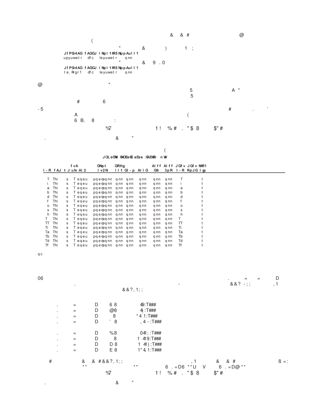
The following will be displayed on your supervisory console:
|
|
|
|
| Down line Load Channel Parameters |
|
|
| |||||
|
|
| STP | FLOW | ENQ/ |
|
| PASS PASS DEST DEST LINK | |||||
CHN | SPD WD BIT PAR | CTRL | ACK ECHO PACE | EIA | XON | CHN NODE A/B | |||||||
01 | 19200 | 8 | 1 | NONE | XON/XOFF | OFF | OFF | OFF | OFF | OFF | 01 | 00 | A |
02 | 19200 | 8 | 1 | NONE | XON/XOFF | OFF | OFF | OFF | OFF | OFF | 02 | 00 | A |
03 | 19200 | 8 | 1 | NONE | XON/XOFF | OFF | OFF | OFF | OFF | OFF | 03 | 00 | A |
04 | 19200 | 8 | 1 | NONE | XON/XOFF | OFF | OFF | OFF | OFF | OFF | 04 | 00 | A |
05 | 19200 | 8 | 1 | NONE | XON/XOFF | OFF | OFF | OFF | OFF | OFF | 05 | 00 | A |
06 | 19200 | 8 | 1 | NONE | XON/XOFF | OFF | OFF | OFF | OFF | OFF | 06 | 00 | A |
07 | 19200 | 8 | 1 | NONE | XON/XOFF | OFF | OFF | OFF | OFF | OFF | 07 | 00 | A |
08 | 19200 | 8 | 1 | NONE | XON/XOFF | OFF | OFF | OFF | OFF | OFF | 08 | 00 | A |
09 | 19200 | 8 | 1 | NONE | XON/XOFF | OFF | OFF | OFF | OFF | OFF | 09 | 00 | A |
10 | 19200 | 8 | 1 | NONE | XON/XOFF | OFF | OFF | OFF | OFF | OFF | 10 | 00 | A |
11 | 19200 | 8 | 1 | NONE | XON/XOFF | OFF | OFF | OFF | OFF | OFF | 11 | 00 | A |
12 | 19200 | 8 | 1 | NONE | XON/XOFF | OFF | OFF | OFF | OFF | OFF | 12 | 00 | A |
13 | 19200 | 8 | 1 | NONE | XON/XOFF | OFF | OFF | OFF | OFF | OFF | 13 | 00 | A |
14 | 19200 | 8 | 1 | NONE | XON/XOFF | OFF | OFF | OFF | OFF | OFF | 14 | 00 | A |
15 | 19200 | 8 | 1 | NONE | XON/XOFF | OFF | OFF | OFF | OFF | OFF | 15 | 00 | A |
16 | 19200 | 8 | 1 | NONE | XON/XOFF | OFF | OFF | OFF | OFF | OFF | 16 | 00 | A |
OK
This display is not a listing of the actual parameters, but shows what can be downline loaded.
7After the remote parameter status screen is displayed, hit Return to display the Remote Source Node Number Group Select screen that permits you to update either 16 channel entries for an MMV1600 series or 32 channel entries for an MMV3200 series.
Source Node For Group A (Channels
Source Node For Group B (Channels
Source Node For Group C(Channels
Source Node For Group D (Channels
Source Node For Group E (Channels
Source Node For Group F (Channels
Source Node For Group G (Channels
Source Node For Group H (Channels
For example, if your MultiMux MMV3200 series is connected to another 32 channel MultiMux with a source node (SN) of 199, set all channels to 199 by entering ATSNGA199<CR>, then ATSNGB199, etc.