RD LEDs ON |
| 2. | Connect composite link cable |
| |
|
|
| |||
between mux and modem. |
|
|
|
| |
Composite link and all | 1. Mux memory failure | 1. | Enter ATL and record all channel |
| |
channels down with |
|
| parameters before running memory |
| |
RD and all channel |
|
| test. Perform memory test by entering |
| |
RCV LEDs ON |
|
| &T2 command. All stored |
| |
parameters will be destroyed. |
|
|
|
| |
|
| 2. | Reconfigure all channel parameters. |
| |
|
| 3. | Call Tech Support for assistance, |
| |
refer to Chapter 8. |
|
|
|
|
|
Flashing RXT LED | 1. High error rate on | 1. View composite link statistics using |
| ||
| communication line |
| #S command, refer to Chapter 5. |
| |
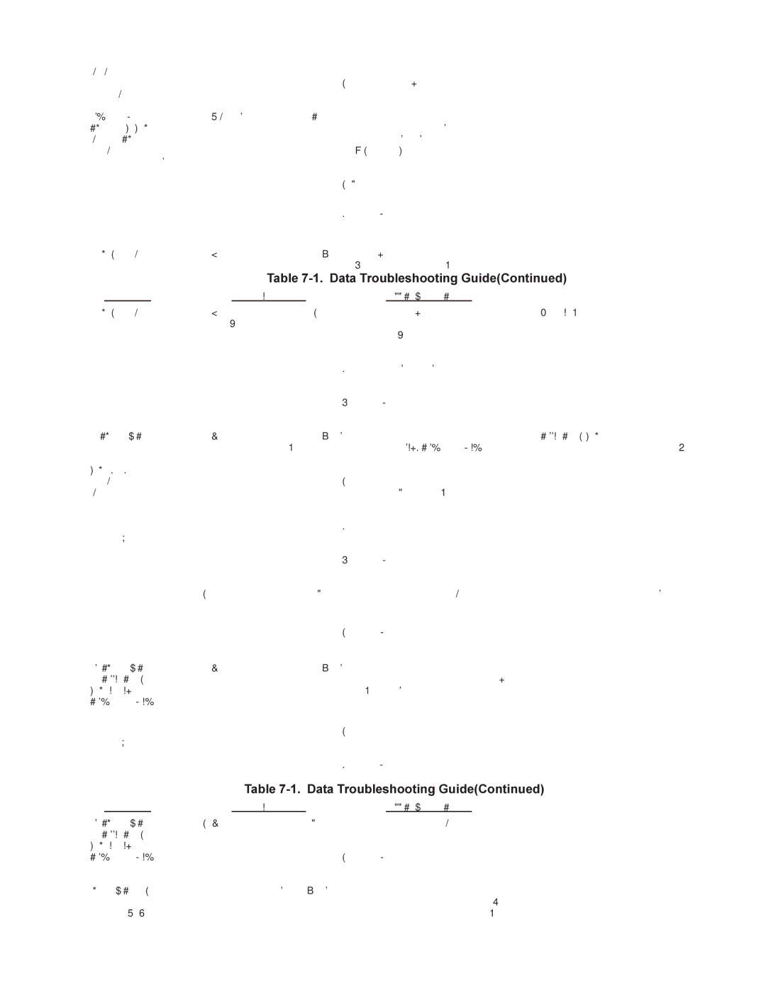
| Table | ||||
Condition | Possible Cause |
|
| Corrective Action |
|
Flashing RXT LED | 1. High error rate on | 2. | Perform local and remote loopback | (Continued) | |
communication line | test, refer to the Local and |
|
|
|
|
|
|
| Communications Line Testing in this |
| |
|
|
| Chapter. |
| |
|
| 3. | Call phone company and verify |
| |
|
|
| communication line. |
| |
|
| 4. | Call Tech Support for assistance, |
| |
refer to Chapter 8. |
|
|
|
|
|
All channel devices not | 1. Incorrect channel | 1. | Verify channel parameter settings for | communicating with | |
parameter settings | all channels, refer to Chapter 5 for the | mux, composite link up | C0 | ||
command. |
|
|
|
|
|
with CO, CTS, XMT and |
|
|
|
|
|
RCV LEDs ON and |
| 2. Change channel parameters to match |
| ||
RD OFF |
|
| channel devices. Refer to Chapter 5 |
| |
for Channel Paramater Commands. |
|
|
|
| |
|
| 3. | Perform channel device testing, refer |
| |
to Channel Device Testing in this |
|
| Chapter. |
| |
|
| 4. | Call Tech Support for assistance, |
| |
refer to Chapter 8. |
|
|
|
|
|
| 2.Channel devices | 1. Refer to cabling diagrams of both mux | incorrectly | ||
cabled | and channel devices. |
|
|
|
|
|
| 2. | Call Tech Support for assistance, |
| |
refer to Chapter 8. |
|
|
|
|
|
Some channel devices | 1. Incorrect channel | 1. | Verify channel parameter settings for |
| |
not communicating | parameter settings |
| for those channel devices, refer to Lx |
| |
with MultiMux and | for those channel devices |
| command in Chapter 5 to display |
| |
composite link up |
|
| channel parameters. |
| |
|
| 2. | Perform channel device testing, refer |
| |
to Channel Device Testing in this |
|
| Chapter. |
| |
|
| 3. | Call Tech Support for assistance, |
| |
refer to Chapter 8. |
|
|
|
|
|
| Table | ||||
Condition | Possible Cause |
Some channel devices 2. | Incorrect cabling for those |
not communicating | channel devices |
with MultiMuxand |
|
composite linkup |
|
refer to Chapter8. |
|
Channel device losing 1. | Flow control not properly |
data | set. |
F2 and
Corrective Action
1.Refer to cabling diagrams of both mux and channel devices.
2.Call Tech Support for assistance,
1.Verify flow control operations for the selected channel device, refer to F0-
Chapter 5.