700 Series Managed Switch User’s Guide for Software v2.1
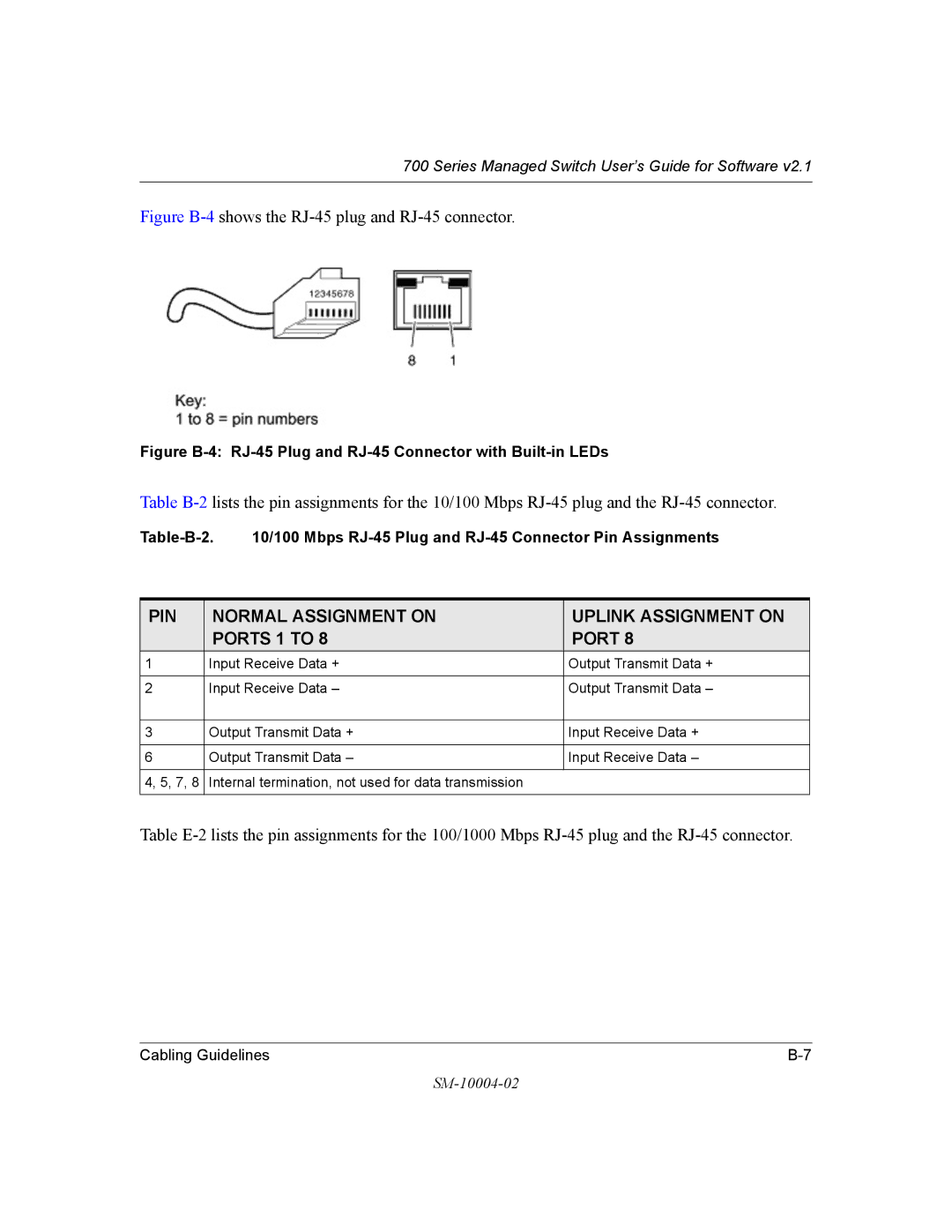
Figure B-4 shows the RJ-45 plug and RJ-45 connector.
Figure B-4: RJ-45 Plug and RJ-45 Connector with Built-in LEDs
Table
PIN | NORMAL ASSIGNMENT ON | UPLINK ASSIGNMENT ON |
| PORTS 1 TO 8 | PORT 8 |
1 | Input Receive Data + | Output Transmit Data + |
|
|
|
2 | Input Receive Data – | Output Transmit Data – |
|
|
|
3 | Output Transmit Data + | Input Receive Data + |
|
|
|
6 | Output Transmit Data – | Input Receive Data – |
|
|
|
4, 5, 7, 8 | Internal termination, not used for data transmission |
|
|
|
|
Table
Cabling Guidelines |