NTI NODEMUX SERIES UNIVERSAL KVM SWITCH
FEATURES AND FUNCTIONS
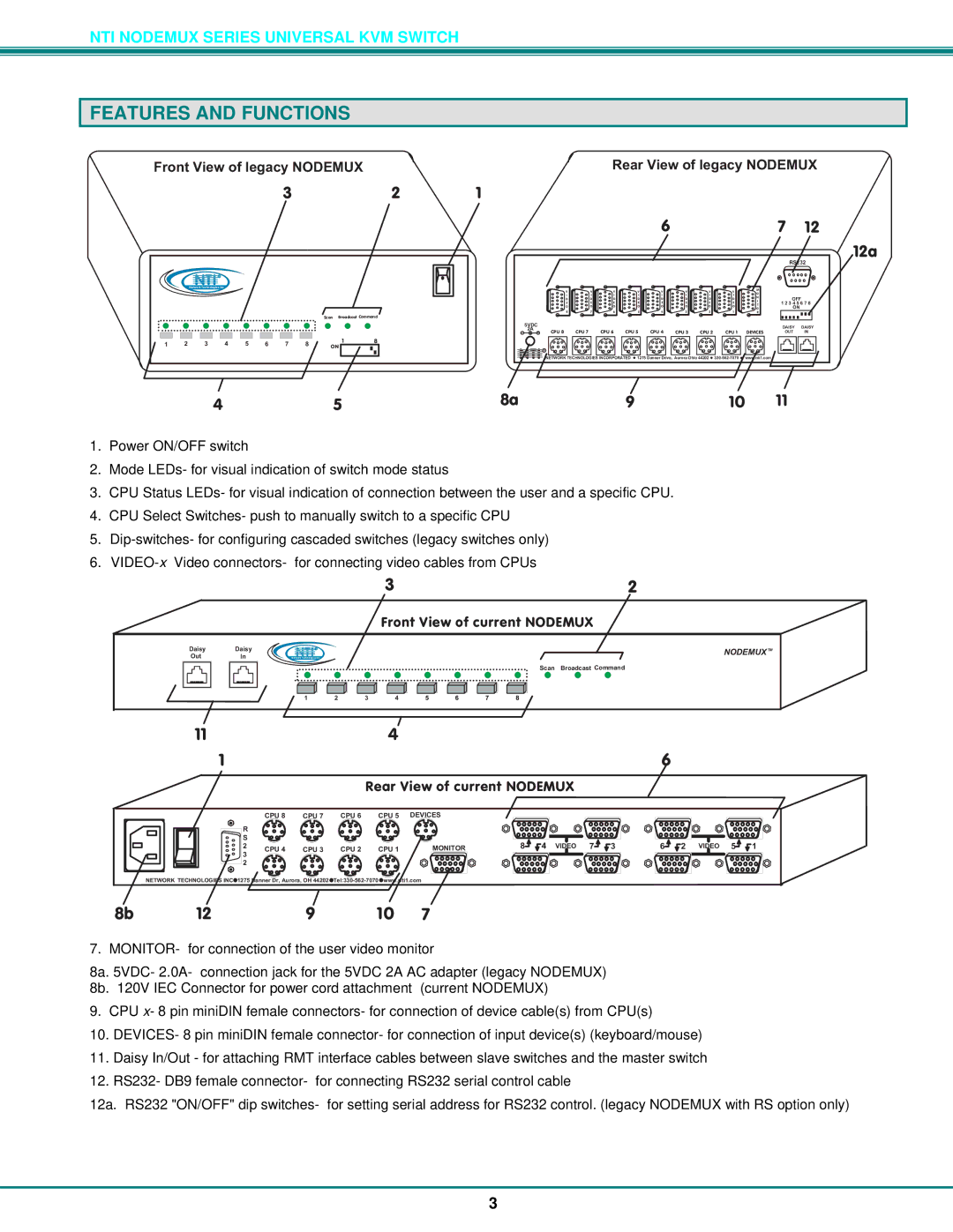
FrontViewoflegacyNODEMUX
3 2
R |
NTI |
NetworkTechnologiesInc
|
|
|
|
|
|
|
| Scan BroadcastCommand | |
1 | 2 | 3 | 4 | 5 | 6 | 7 | 8 | 1 | 8 |
ON |
| ||||||||
|
| RearViewoflegacyNODEMUX | |||||||||
1 |
|
|
|
|
|
|
|
|
|
| |
|
|
|
| 6 |
|
|
| 7 12 | |||
|
|
|
|
|
|
|
|
| RS232 | ||
V | V | V | V | V | V | V | V | M |
|
| |
O |
|
| |||||||||
I | I | I | I | I | I | I | I | N |
|
| |
D | D | D | D | D | D | D | D | OFF | |||
I | |||||||||||
E | E | E | E | E | E | E | E | T | 12345678 | ||
O | O | O | O | O | O | O | O | O | ON |
| |
8 | 7 | 6 | 5 | 4 | 3 | 2 | 1 | R |
|
| |
5VDC |
|
|
|
|
|
|
|
| DAISY | DAISY | |
|
|
|
|
|
|
|
| ||||
CPU7 | CPU6 | CPU5 | CPU4 | CPU3 | CPU2 | CPU1 | DEVICES | OUT | IN | ||
R |
|
|
|
NTINETWORKTECHNOLOGIESINCORPORATED | 1275DannerDrive,AuroraOhio44202 | www.nti1.com |
12a
4 | 5 | 8a | 9 | 10 | 11 |
1.Power ON/OFF switch
2.Mode LEDs- for visual indication of switch mode status
3.CPU Status LEDs- for visual indication of connection between the user and a specific CPU.
4.CPU Select Switches- push to manually switch to a specific CPU
5.
6.
32
FrontViewofcurrentNODEMUX
Daisy Daisy
Out In
R |
NTI |
NetworkTechnologiesInc
NODEMUXTM
Scan BroadcastCommand
1 2 3 4 5 6 7 8
114
1
|
|
|
| RearViewofcurrentNODEMUX |
|
| |||
| CPU8 | CPU7 | CPU6 | CPU5 | DEVICES |
|
|
|
|
R |
|
|
|
|
|
|
|
|
|
S |
|
|
|
|
|
|
|
|
|
2 | CPU4 | CPU3 | CPU2 | CPU1 | MONITOR | 8 | 4 VIDEO | 7 | 3 |
3 |
|
|
|
| |||||
|
|
|
|
|
|
|
|
| |
2 |
|
|
|
|
|
|
|
|
|
NETWORKTECHNOLOGIESINC 1275DannerDr,Aurora,OH44202 |
|
|
|
| |||||
6
6 | 2 VIDEO | 5 | 1 |
8b 12 9 10 7
7. MONITOR- for connection of the user video monitor
8a. 5VDC- 2.0A- connection jack for the 5VDC 2A AC adapter (legacy NODEMUX)
8b. 120V IEC Connector for power cord attachment (current NODEMUX)
9.CPU x- 8 pin miniDIN female connectors- for connection of device cable(s) from CPU(s)
10.DEVICES- 8 pin miniDIN female connector- for connection of input device(s) (keyboard/mouse)
11.Daisy In/Out - for attaching RMT interface cables between slave switches and the master switch
12.RS232- DB9 female connector- for connecting RS232 serial control cable
12a. RS232 "ON/OFF" dip switches- for setting serial address for RS232 control. (legacy NODEMUX with RS option only)
3