NTI NODEMUX SERIES UNIVERSAL KVM SWITCH
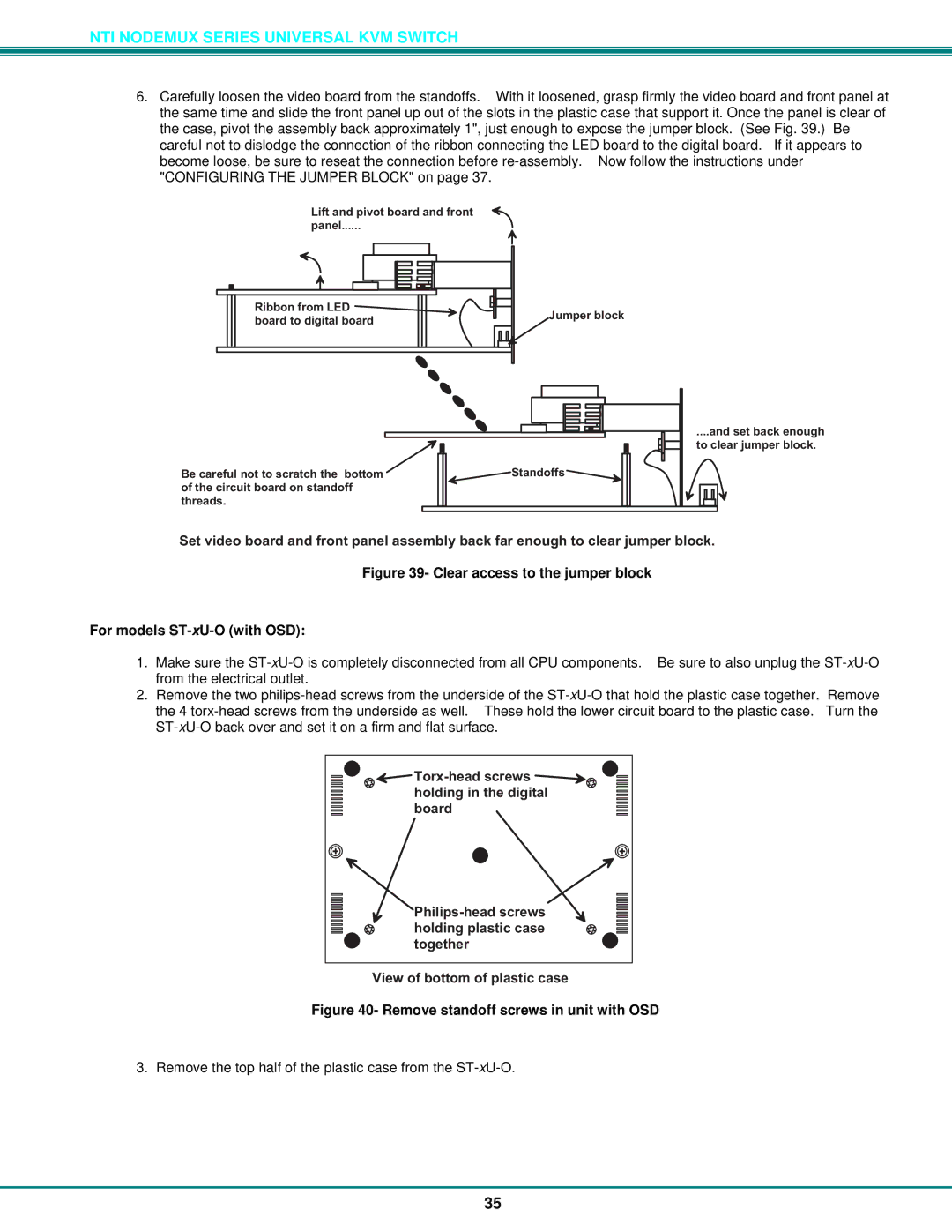
6.Carefully loosen the video board from the standoffs. With it loosened, grasp firmly the video board and front panel at the same time and slide the front panel up out of the slots in the plastic case that support it. Once the panel is clear of the case, pivot the assembly back approximately 1", just enough to expose the jumper block. (See Fig. 39.) Be careful not to dislodge the connection of the ribbon connecting the LED board to the digital board. If it appears to become loose, be sure to reseat the connection before
Liftandpivotboardandfront ![]() panel .
panel .
RibbonfromLED | Jumperblock | |
boardtodigitalboard | ||
|
Becarefulnottoscratchthebotom ofthecircuitboardonstandof threads.
.andsetbackenough toclearjumperblock.
Standofs |
Setvideoboardandfrontpanelassemblybackfarenoughtoclearjumperblock.
Figure 39- Clear access to the jumper block
For models ST-xU-O (with OSD):
1.Make sure the
2.Remove the two
![]()
![]()
Viewofbotomofplasticcase
Figure 40- Remove standoff screws in unit with OSD
3. Remove the top half of the plastic case from the
35