NTI NODEMUX SERIES UNIVERSAL KVM SWITCH
INSTALLATION
1.Turn OFF power to all CPUs that will be connected to the NODEMUX before connecting or disconnecting any cables to or from them.
!WARNING! DAMAGE MAY OCCUR TO THE CPU IF POWER IS NOT DISCONNECTED BEFORE CONNECTING OR DISCONNECTING CABLES.
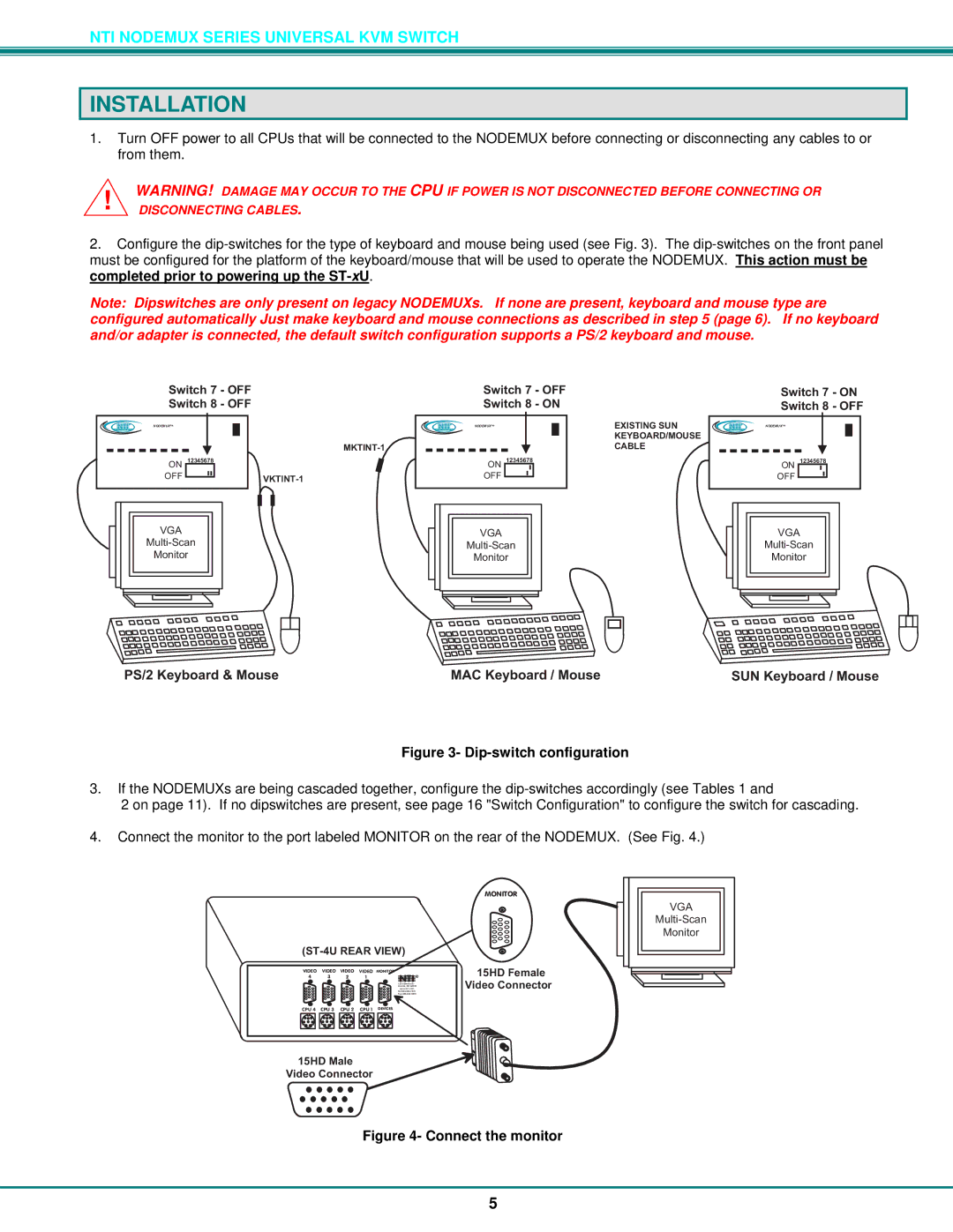
2.Configure the
Note: Dipswitches are only present on legacy NODEMUXs. If none are present, keyboard and mouse type are configured automatically Just make keyboard and mouse connections as described in step 5 (page 6). If no keyboard and/or adapter is connected, the default switch configuration supports a PS/2 keyboard and mouse.
NTI NODEMUXTM
ON 12345678 |
|
OFF | |
|
VGA
Monitor
NTI | NODEMUXTM | EXISTINGSUN | NTI | NODEMUXTM |
|
|
| ||
|
| KEYBOARD/MOUSE |
|
|
|
| CABLE |
|
|
ON 12345678 | ON 12345678 |
OFF | OFF |
|
|
|
|
|
|
|
|
|
|
|
|
|
|
|
|
|
|
|
|
|
|
|
|
|
|
|
|
|
|
|
|
|
|
|
| VGA |
|
|
|
|
|
|
|
|
|
|
|
|
| VGA |
|
|
| ||||
|
|
|
|
|
|
|
|
|
|
|
|
|
|
|
|
|
|
|
|
|
|
| ||||||
|
|
|
|
|
|
|
|
|
|
|
|
|
|
|
|
|
|
| ||||||||||
|
|
|
|
|
|
| Monitor |
|
|
|
|
|
|
|
|
|
|
|
|
| Monitor |
|
|
| ||||
|
|
|
|
|
|
|
|
|
|
|
|
|
|
|
|
|
|
|
|
|
|
|
|
|
|
|
|
|
|
|
|
|
|
|
|
|
|
|
|
|
|
|
|
|
|
|
|
|
|
|
|
|
|
|
|
|
|
|
|
|
|
|
|
|
|
|
|
|
|
|
|
|
|
|
|
|
|
|
|
|
|
|
|
|
|
|
|
|
|
|
|
|
|
|
|
|
|
|
|
|
|
|
|
|
|
|
|
|
|
|
|
|
|
|
|
|
|
|
|
|
|
|
|
|
|
|
|
|
|
|
|
|
|
|
|
|
|
|
|
|
|
|
|
|
|
|
|
|
|
|
|
|
|
|
|
|
|
|
|
|
|
|
|
|
|
|
|
|
|
|
|
|
|
PS/2Keyboard&Mouse | MACKeyboard/Mouse | SUNKeyboard/Mouse |
Figure 3- Dip-switch configuration
3.If the NODEMUXs are being cascaded together, configure the
2 on page 11). If no dipswitches are present, see page 16 "Switch Configuration" to configure the switch for cascading.
4.Connect the monitor to the port labeled MONITOR on the rear of the NODEMUX. (See Fig. 4.)
(ST-4UREARVIEW)
VIDEO | VIDEO | VIDEO | VIDEO MONITOR | NTI | |
4 | 3 | 2 | 1 | ||
R | |||||
|
|
|
| 1275DannerDr | |
|
|
|
| Aurora,OH44202 | |
|
|
|
| www.nti1.com | |
|
|
|
| ||
|
|
|
|
MONITOR
15HDFemale VideoConnector
VGA
Monitor
CPU4 CPU3 CPU2 CPU1 DEVICES
15HDMale VideoConnector
Figure 4- Connect the monitor
5