NTI NODEMUX SERIES UNIVERSAL KVM SWITCH
Command Mode (Cont’d)
Function:Keystroke:
Sets scan | Ctrl | |
each port | ||
| ||
Selects a specific port | Ctrl |
Selects the first port on the switch
Home
Selects the last port on the switch | End | |
Enters Search Mode and adds a character | ||
to search string and selects the CPU’s | ||
name that matches best. | ||
| ||
Switch to a selected port | Enter | |
Exit Command Mode | Esc |
+ T | - | - | - | (xxx from 002 to 255. ie. t002 | |||
x | x | x | would set the | ||||
for 2 seconds) |
+ P - | x | - | x |
|
|
| (Pxx would be P01, P02, etc.) | ||
|
|
|
|
(Type any alphabetical or numeric character)
Note: The user must exit Command Mode to type to a CPU.
To exit Command Mode, either hold down any touch- switch on the front panel for more than 2 seconds, OR press <ESC>.
FYI: If the Touch Screen Support option is present, the user can also exit the Main Command mode menu by tapping once on
The mouse can also be used to control Command Mode. The mouse cursor can be moved to the Scan, Help, and Exit fields where the user can then click on the left mouse button to perform that function. Ports listed on the screen can be selected by moving the cursor onto that port and clicking. Clicking twice on a selected port will switch to that port and exit Command Mode. To change the displayed ports on the screen simply click on the up and down arrows located to the right of the port names displayed.
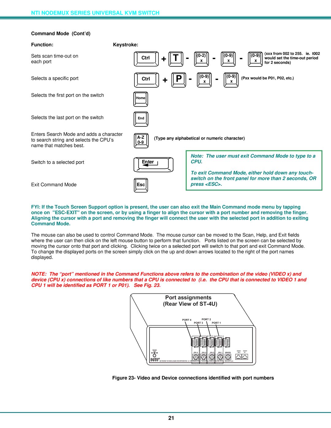
NOTE: The “port” mentioned in the Command Functions above refers to the combination of the video (VIDEO x) and device (CPU x) connections of like numbers that a CPU is connected to (i.e. the CPU that is connected to VIDEO 1 and CPU 1 will be identified as PORT 1 or P01). See Fig. 23.
Portassignments (RearViewofST-4U)
PORT4 PORT2
PORT3 PORT1
| V | V | V | V | M |
| O | ||||
| I | I | I | I | N |
| D | D | D | D | I |
| E | E | E | E | T |
| O | O | O | O | O |
| 4 | 3 | 2 | 1 | R |
5VDC |
|
|
|
|
|
| CPU4 | CPU3 | CPU2 | CPU1 | DEVICES |
R |
|
|
|
NTINETWORKTECHNOLOGIESINCORPORATED | 1275DannerDrive,AuroraOhio44202 | www.nti1.com |
DAISY DAISY OUT IN
Figure 23- Video and Device connections identified with port numbers
21