NTI NODEMUX SERIES UNIVERSAL KVM SWITCH
CASCADING
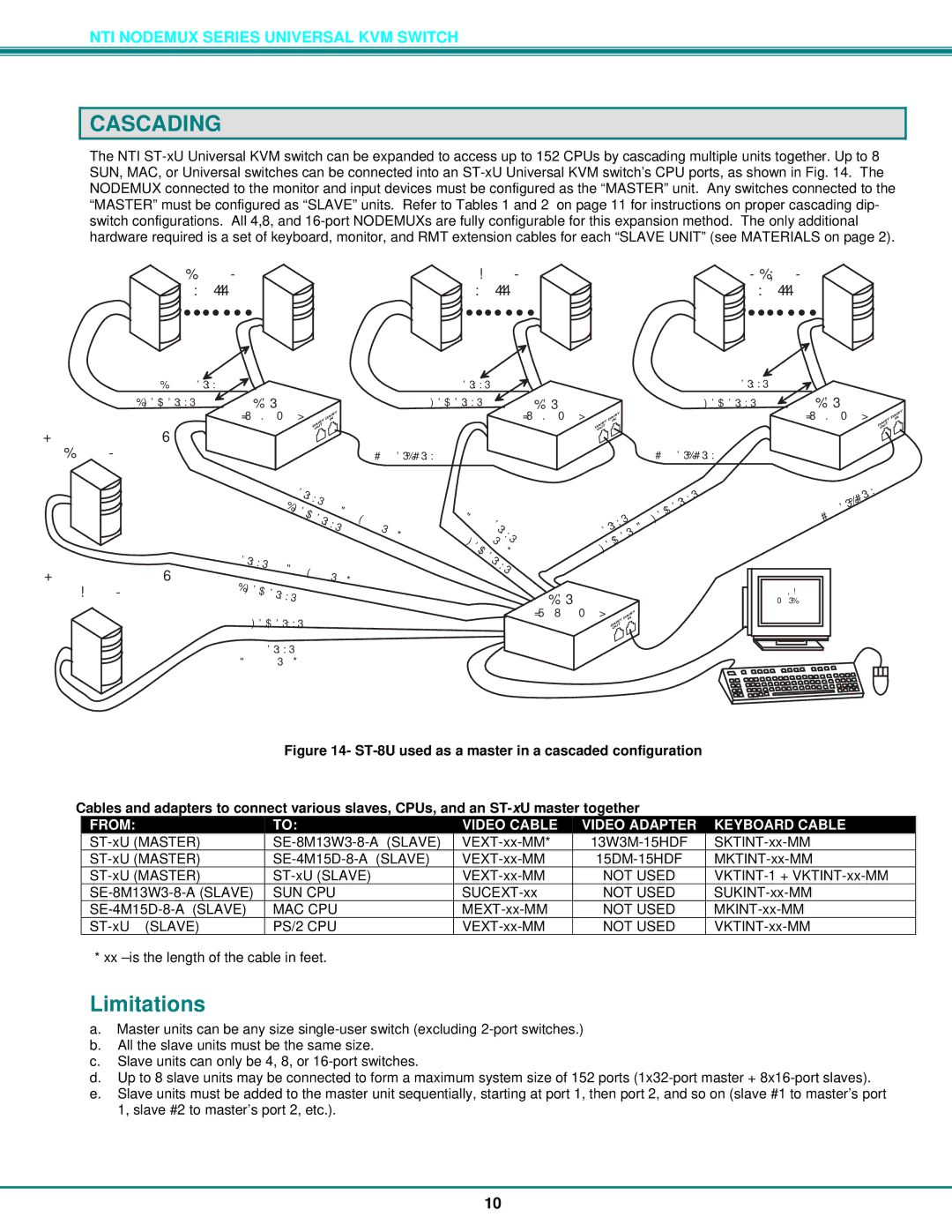
The NTI ST-xU Universal KVM switch can be expanded to access up to 152 CPUs by cascading multiple units together. Up to 8 SUN, MAC, or Universal switches can be connected into an ST-xU Universal KVM switch’s CPU ports, as shown in Fig. 14. The NODEMUX connected to the monitor and input devices must be configured as the “MASTER” unit. Any switches connected to the “MASTER” must be configured as “SLAVE” units. Refer to Tables 1 and 2 on page 11 for instructions on proper cascading dip- switch configurations. All 4,8, and 16-port NODEMUXs are fully configurable for this expansion method. The only additional hardware required is a set of keyboard, monitor, and RMT extension cables for each “SLAVE UNIT” (see MATERIALS on page 2).
SUNCPU | MACCPU | PS/2CPU |
x1.16 | x1.16 | x1.16 |
SUCEXT-xx | | MEXT-xx-MM | | VEXT-xx-MM | |
SKTINT-xx-MM | ST-16U | MKTINT-xx-MM | ST-16U | VKTINT-xx-MM | ST-16U |
| (slaveunit | | (slaveunit | | (slaveunit |
VE | | | | | | | | | | |
| XT | | | | | | | | |
| | | - | | | | | | | | |
| | | xx | | | | | | |
| S | | | - | | | | | | |
| | | | MM | | | | | |
| K | | | | | + | | | | |
| | TIN | | | | | | |
| | | | 13W | | | |
| | | | T | | | | |
| | | | | - | | | | M | |
| | | | | xx | | | |
| | | | | | - | 3 | | |
| | | | | | MM | | | - |
| | | | | | | | | | | 15H |
| | | | | | | | | | | DF |
VEXT- | | | | | | | | | | | |
xx- | | | | | | | | | | | |
MM+ | | | | | | | | | |
| 13W3M | | | | | | |
| | | | | - | | | | |
SKTINT | | | | | | 15HDF | | | |
| | | | | | | | | | |
-x | | | | | | | | | | |
| x- | | | | | | | | | |
| MM | | | | | | | | |
MKTINT-xx-MM | | | | | | | |
VEXT-xx-MM | | | | | | | | |
+15DM-15HDF | | | | | | | |
| V | |
+ | EXT | |
1 | - |
| 5 |
| DM | x |
| | x |
MKTINT | - |
| | - |
| | | MM |
| | -15HDF |
| | xx |
| | | - |
| | | MM |
| | | | | | M |
| | | | | | M |
| | | | | | - |
| | | | | | x |
| | | | | | x |
| | | | | | - |
| | | | | | T |
| | | | M | TIN |
| | | | M | | VK |
| | x | |
| | | - | | |
| | x | | + |
| | - | | |
| | T | | 1 | |
X | | - | |
E | | T | | |
V | | IN | | |
| | T | | | | |
| K | | | | |
V | | | | |
ST-8U (masterunit
x -x -SR T X E R
VGA
Multi-Scan
Monitor
Figure 14- ST-8U used as a master in a cascaded configuration
Cables and adapters to connect various slaves, CPUs, and an ST-xU master together
| FROM: | TO: | VIDEO CABLE | VIDEO ADAPTER | KEYBOARD CABLE |
|
| ST-xU (MASTER) | SE-8M13W3-8-A (SLAVE) | VEXT-xx-MM* | 13W3M-15HDF | SKTINT-xx-MM |
| ST-xU (MASTER) | SE-4M15D-8-A (SLAVE) | VEXT-xx-MM | 15DM-15HDF | MKTINT-xx-MM |
| ST-xU (MASTER) | ST-xU (SLAVE) | VEXT-xx-MM | NOT USED | VKTINT-1 + VKTINT-xx-MM |
| SE-8M13W3-8-A (SLAVE) | SUN CPU | SUCEXT-xx | NOT USED | SUKINT-xx-MM |
| SE-4M15D-8-A (SLAVE) | MAC CPU | MEXT-xx-MM | NOT USED | MKINT-xx-MM |
| ST-xU (SLAVE) | PS/2 CPU | VEXT-xx-MM | NOT USED | VKTINT-xx-MM |
* xx –is the length of the cable in feet.
Limitations
a.Master units can be any size single-user switch (excluding 2-port switches.)
b.All the slave units must be the same size.
c.Slave units can only be 4, 8, or 16-port switches.
d.Up to 8 slave units may be connected to form a maximum system size of 152 ports (1x32-port master + 8x16-port slaves).
e.Slave units must be added to the master unit sequentially, starting at port 1, then port 2, and so on (slave #1 to master’s port 1, slave #2 to master’s port 2, etc.).