NTI NODEMUX SERIES UNIVERSAL KVM SWITCH
NOTE: Before proceeding, it is important to discharge any static charge you may be carrying by touching any large metal object (away from the
4.Firmly grasp the front and rear panel and slide the entire assembly out of the lower case.
5.Remove the jack screws from the video and monitor connectors on the rear panel. Remove the rear panel from the assembly.
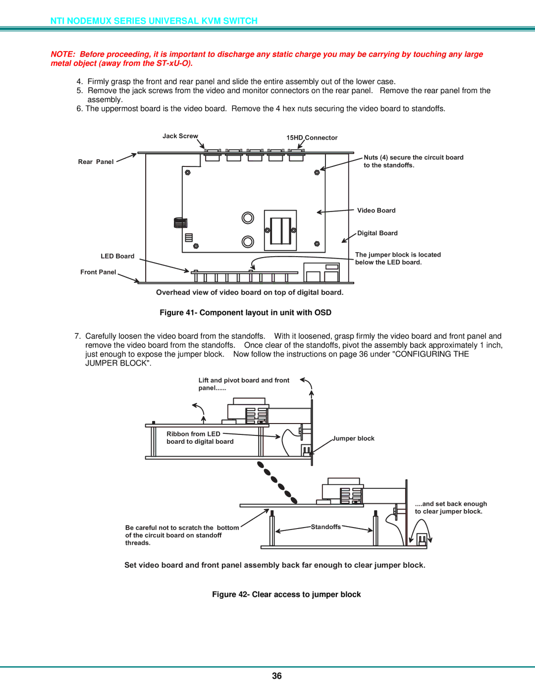
6.The uppermost board is the video board. Remove the 4 hex nuts securing the video board to standoffs.
JackScrew15HDConnector
RearPanel![]()
LEDBoard
FrontPanel
Nuts(4)securethecircuitboard |
tothestandofs. |
VideoBoard |
DigitalBoard |
Thejumperblockislocated |
belowtheLEDboard. |
Overheadviewofvideoboardontopofdigitalboard.
Figure 41- Component layout in unit with OSD
7.Carefully loosen the video board from the standoffs. With it loosened, grasp firmly the video board and front panel and remove the video board from the standoffs. Once clear of the standoffs, pivot the assembly back approximately 1 inch, just enough to expose the jumper block. Now follow the instructions on page 36 under "CONFIGURING THE JUMPER BLOCK".
Liftandpivotboardandfront ![]() panel .
panel .
RibbonfromLED | Jumperblock | |
boardtodigitalboard | ||
|
Becarefulnottoscratchthebotom ofthecircuitboardonstandof threads.
.andsetbackenough toclearjumperblock.
Standofs |
Setvideoboardandfrontpanelassemblybackfarenoughtoclearjumperblock.
Figure 42- Clear access to jumper block
36