[a]
.,lto"...... ~ ~
~~
II
CJ~-~
[b][c]
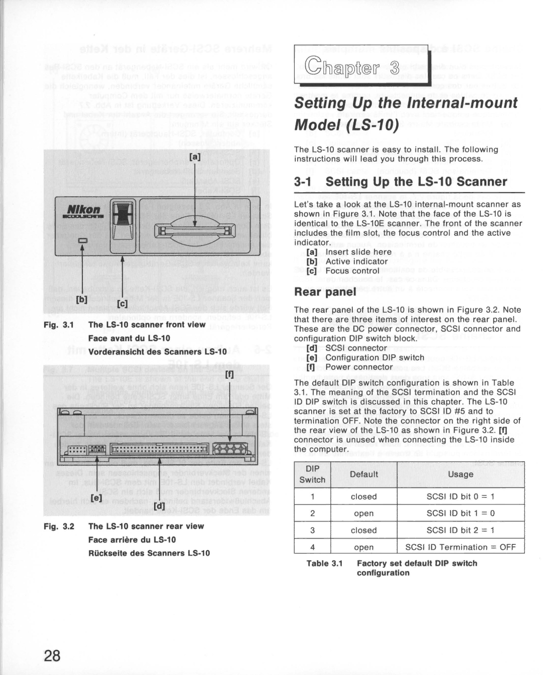
Fig. 3.1 The LS-10 scanner front view
Face avant du LS-10
Vorderansicht des Scanners LS-10
[I]
II
II d:::::IIJIIIIIIIl"O:::::::::::::::::::::::::d1
[e]
[d]
Fig. 3.2 The LS-10 scanner rear view
Face arriere du LS-10
Riickselte des Scanners LS-10
~lhliID[lilfr® IT' ~ I
Setting Up the Internal-mount
Model (LS-10)
The
3-1 SeHing Up the LS-10 Scanner
Let'stake a look at the
[a]Insert slide here
[b]Active indicator
[c]Focus control
Rear panel
The rear panel of the
[d]SCSI connector
[e]Configuration DIP switch
[I]Power connector
The default DIP switch configuration is shown in Table
3.1.The meaning of the SCSI termination and the SCSI 10 DIP switch is discussed in this chapter. The
DIP | Default | Usage | ||
Switch | ||||
|
|
| ||
1 | closed | SCSI 10 bit 0 =1 | ||
2 | open | SCSI 10 | bit 1 =0 | |
3 | closed | SCSI 10 | bit 2 =1 | |
4 | open | SCSI 10 Termination =OFF | ||
Table 3.1 | Factory set default DIP switch | |||
| configuration |
| ||
28