[b)
[a]
j
~ ~
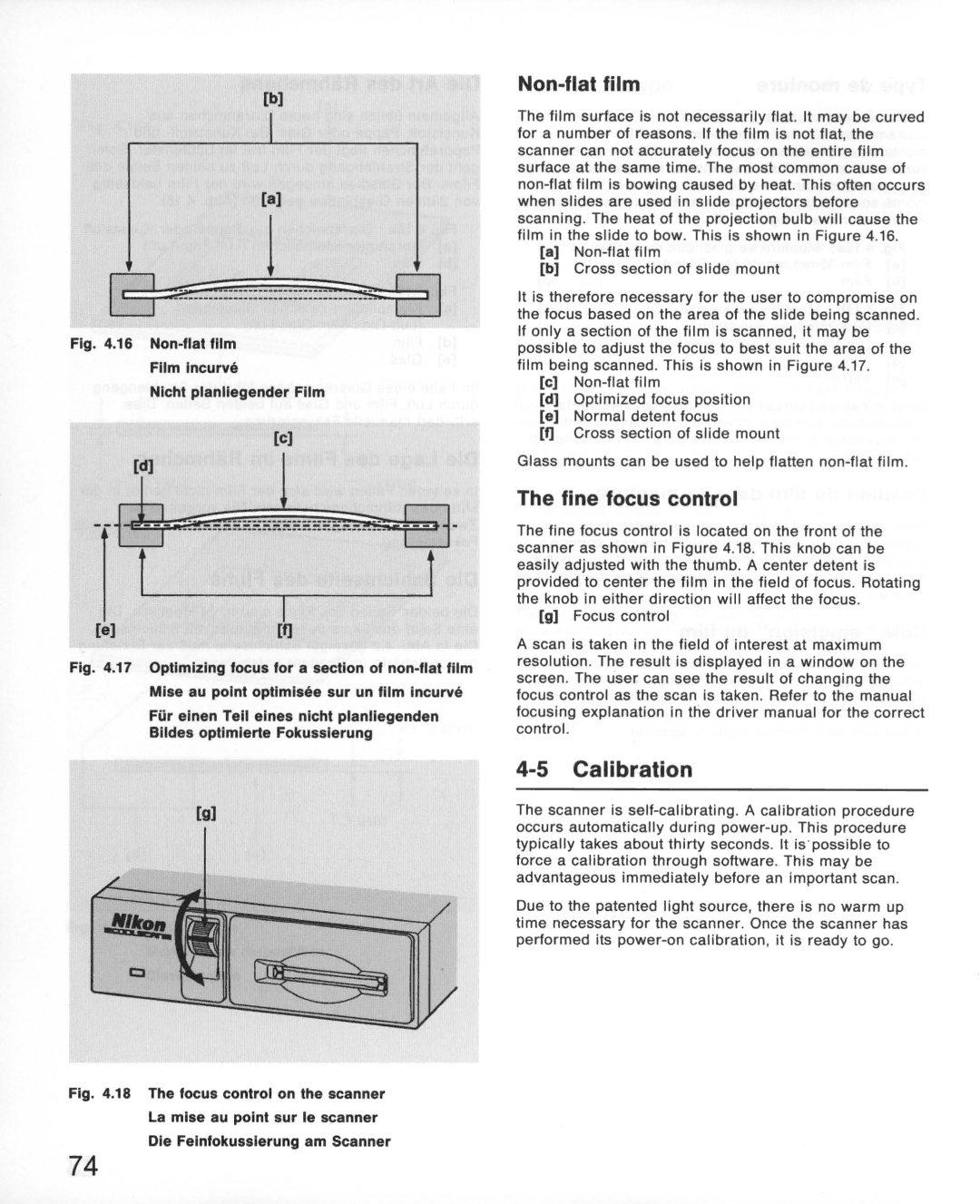
Fig. 4.16 Non-flat film
Film Incurve
Nlcht planliegender Film
[c)
| [d] | J | ~ | |
~ | _______ m _____ | |||
| I | |||
[e) | I |
|
| |
[ij |
|
| ||
Fig. 4.17 Optimizing focus for a section of non-flat film Mise au pOint optlmlsee sur un film Incurve
Fur einen Tell elnes nlcht planllegenden
Blldes optlmlerte Fokusslerung
[g)
Fig. 4.18 The focus control on the scanner La mise au pOint sur Ie scanner Die Feinfokusslerung am Scanner
Non-flat film
The film surface is not necessarily flat. It may be curved for a number of reasons . If the film is not flat, the scanner can not accurately focus on the entire film surface at the same time. The most common cause of
[a]
[b)Cross section of slide mount
It is therefore necessary for the user to compromise on the focus based on the area of the slide being scanned . If only a section of the film is scanned, it may be possible to adjust the focus to best suit the area of the film being scanned . This is shown in Figure 4.17.
[c)
[d)Optimized focus position
[e)Normal detent focus
[f]Cross section of slide mount
Glass mounts can be used to help flatten
The fine focus control
The fine focus control is located on the front of the scanner as shown in Figure 4.18. This knob can be easily adjusted with the thumb. A center detent is provided to center the film in the field of focus . Rotating the knob in either direction will affect the focus .
[g)Focus control
A scan is taken in the field of interest at maximum resolution. The result is displayed in a window on the screen . The user can see the result of changing the focus control as the scan is taken . Refer to the manual focusing explanation in the driver manual for the correct control.
4-5 Calibration
The scanner is
Due to the patented light source, there is no warm up time necessary for the scanner. Once the scanner has performed its
74
