[8][b)

[g)[e)

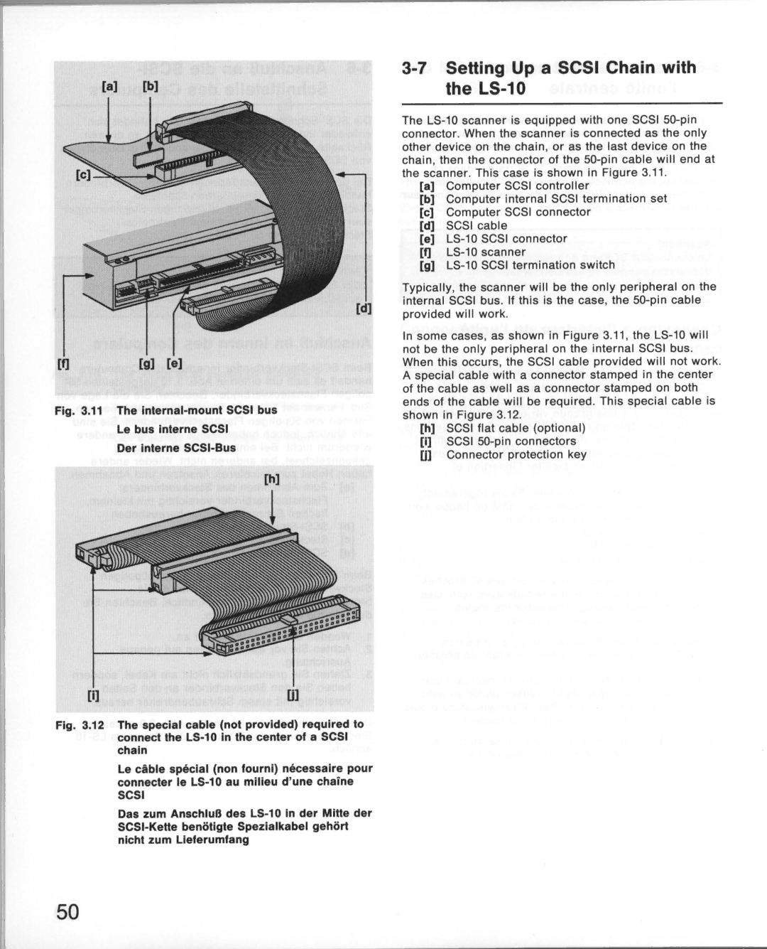
Fig. 3.11 The internal-mount SCSI bus

Le bus interne SCSI

Der Interne SCSI-Bus

[h)

[i)[j]

Fig. 3.12 The special cable (not provided) required to connect the LS-10 In the center of a SCSI chain

Le cable special (non fourni) necessalre pour connecter Ie LS-10 au milieu d'unechaine

SCSI

Das zum AnschluB des LS-10 In der MIHe der SCSI-KeHe beniitigte Spezialkabel gehiirt nlcht zum Lleferumfang

3-7 SeHing Up a SCSI Chain with the LS-10

The LS-10 scanner is equipped with one SCSI 50-pin connector. When the scanner is connected as the only other device on the chain, or as the last device on the chain, then the connector of the 50-pin cable will end at the scanner. This case is shown in Figure 3.11 .

[a]Computer SCSI controller

[b]Computer internal SCSI termination set

[c]Computer SCSI connector

[d]SCSI cable

[e]LS-10 SCSI connector

[I]LS-10 scanner

[g]LS-10 SCSI termination switch

Typically, the scanner will be the only peripheral on the internal SCSI bus . If this is the case, the 50-pin cable provided will work.

In some cases, as shown in Figure 3.11 . the LS-10 will not be the only peripheral on the internal SCSI bus. When this occurs . the SCSI cable provided will not work. A special cable with a connector stamped in the center of the cable as well as a connector stamped on both ends of the cable will be required . This special cable is shown in Figure 3.12.

[h]SCSI flat cable (optional)

[I]SCSI 50-pin connectors Ul Connector protection key

50

Page 50
Image 50
Nikon LS-10E instruction manual SeHing Up a Scsi Chain with the LS-10