II'llo"- ~[
[8]
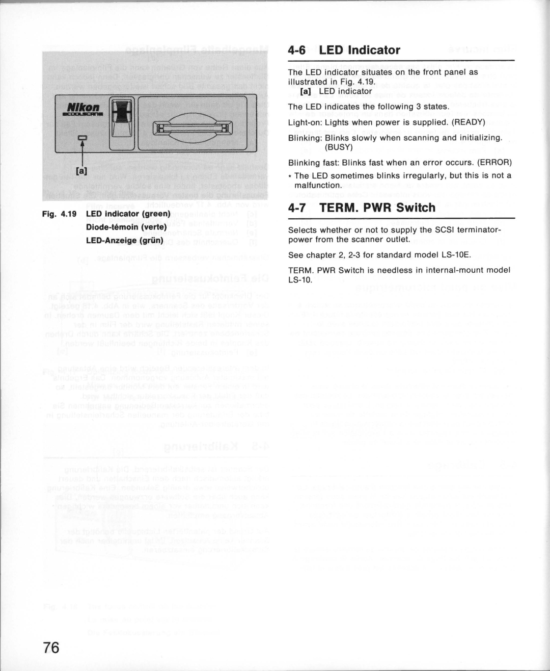
Fig. 4.19 LED Indicator (green)
Diode-temoin (verte)
LED-Anzeige (griin)
4-6 LED Indicator
The LED indicator situates on the front panel as illustrated in Fig . 4.19.
[a]LED indicator
The LED indicates the following 3 states.
Blinking: Blinks slowly when scanning and initializing. (BUSY)
Blinking fast: Blinks fast when an error occurs . (ERROR)
*The LED sometimes blinks irregularly. but this is not a malfunction.
4-7 TERM. PWR Switch
Selects whether or not to supply the SCSI terminator- power from the scanner outlet.
See chapter 2.
TERM. PWR Switch is needless in
76