Using the Passport 8100 Modules
Note: Nortel Networks recommends using the Passport 8190SM module to configure and manage your switch. The Comm port on the Passport 8132TX module is active only when no Passport 8190SM module is present and when the Passport 8132TX module is operating as the master module.
The Comm port on the Passport 8132TX module is configured as a data communications equipment (DCE) connector. Be sure that your
LEDs
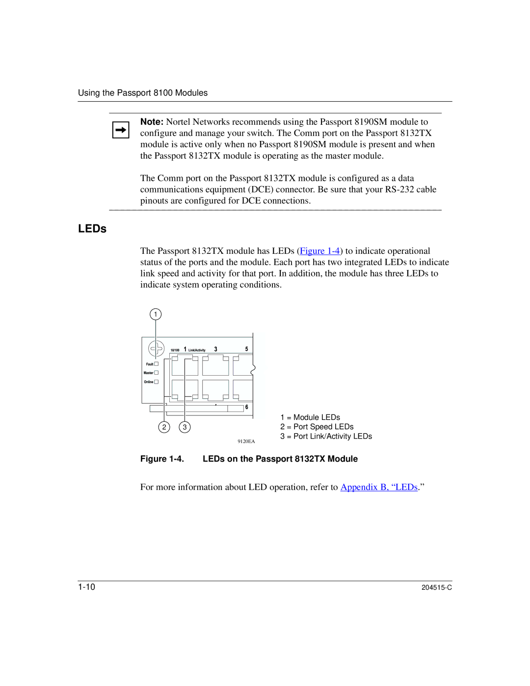
The Passport 8132TX module has LEDs (Figure
1 |
|
2 | 3 |
| 9120EA |
1 = Module LEDs
2 = Port Speed LEDs
3 = Port Link/Activity LEDs
Figure 1-4. LEDs on the Passport 8132TX Module
For more information about LED operation, refer to Appendix B, “LEDs.”
|