Media Dependent Adapters
| ||||
|
|
|
| Link |
|
|
|
| Phy Select |
|
|
|
| Activity |
TX | RX | TX | RX | |
|
|
|
| |
|
| Link |
|
| Phy |
|
| Activity |
TX | RX | |
|
|
2 | 1 | 2 | 1 |
9216EA
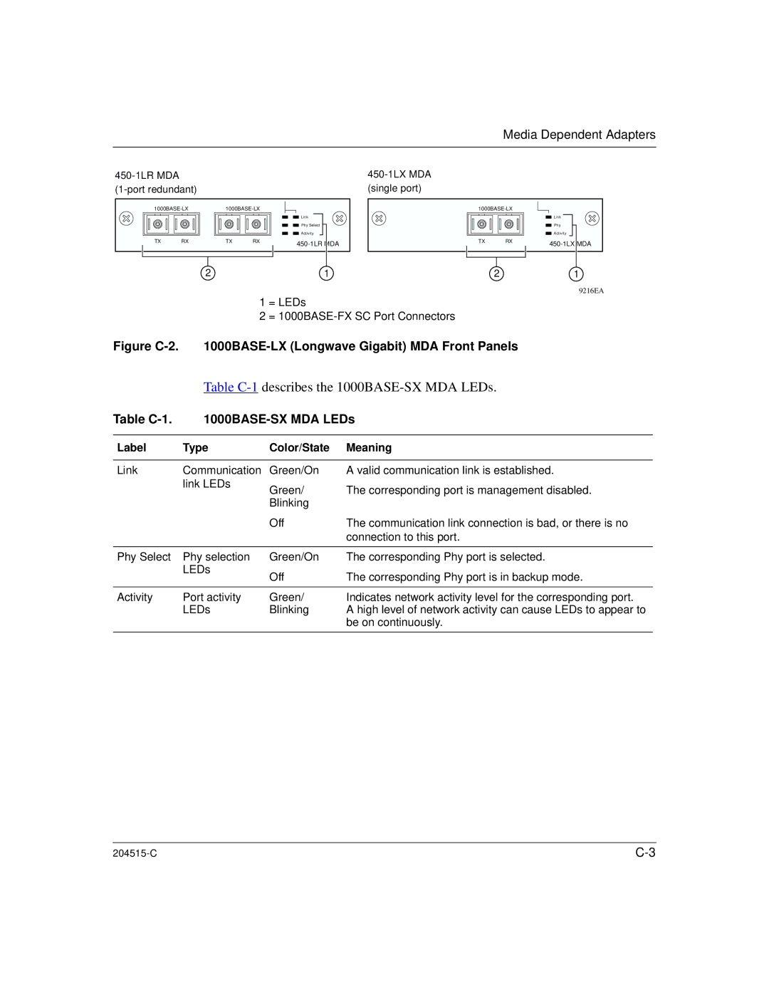
1 = LEDs
2 =
Figure C-2. 1000BASE-LX (Longwave Gigabit) MDA Front Panels
Table C-1 describes the 1000BASE-SX MDA LEDs.
Table |
| ||
|
|
|
|
Label | Type | Color/State | Meaning |
|
|
|
|
Link | Communication | Green/On | A valid communication link is established. |
| link LEDs | Green/ | The corresponding port is management disabled. |
|
| ||
|
| Blinking |
|
|
| Off | The communication link connection is bad, or there is no |
|
|
| connection to this port. |
|
|
|
|
Phy Select | Phy selection | Green/On | The corresponding Phy port is selected. |
| LEDs | Off | The corresponding Phy port is in backup mode. |
|
| ||
|
|
|
|
Activity | Port activity | Green/ | Indicates network activity level for the corresponding port. |
| LEDs | Blinking | A high level of network activity can cause LEDs to appear to |
|
|
| be on continuously. |
|
|
|
|
|