Using the Passport 8100 Modules
LEDs
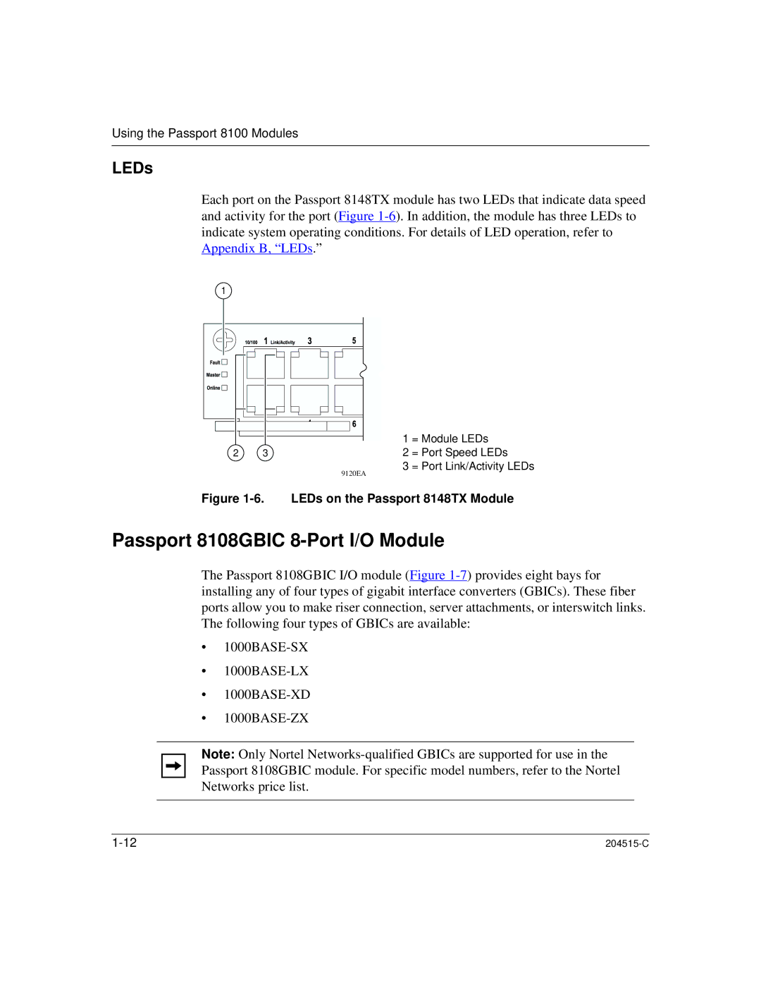
Each port on the Passport 8148TX module has two LEDs that indicate data speed and activity for the port (Figure
1 |
|
2 | 3 |
| 9120EA |
1 = Module LEDs
2 = Port Speed LEDs
3 = Port Link/Activity LEDs
Figure 1-6. LEDs on the Passport 8148TX Module
Passport 8108GBIC 8-Port I/O Module
The Passport 8108GBIC I/O module (Figure
•
•
•
•
Note: Only Nortel
|