14(86) | Technical data |
4.TECHNICAL DATA
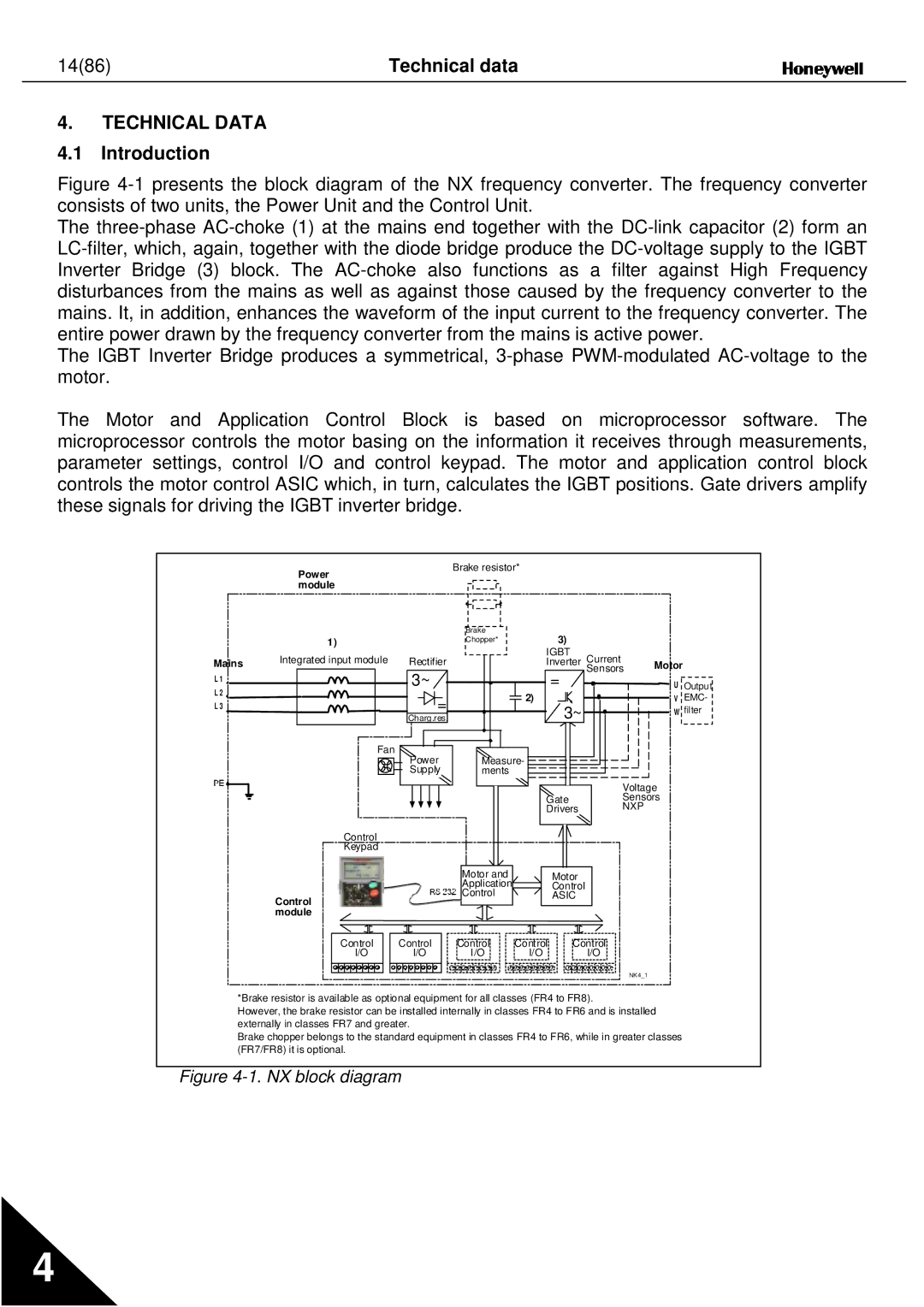
4.1 Introduction
Figure 4-1 presents the block diagram of the NX frequency converter. The frequency converter consists of two units, the Power Unit and the Control Unit.
The three-phase AC-choke (1) at the mains end together with the DC-link capacitor (2) form an LC-filter, which, again, together with the diode bridge produce the DC-voltage supply to the IGBT Inverter Bridge (3) block. The AC-choke also functions as a filter against High Frequency disturbances from the mains as well as against those caused by the frequency converter to the mains. It, in addition, enhances the waveform of the input current to the frequency converter. The entire power drawn by the frequency converter from the mains is active power.
The IGBT Inverter Bridge produces a symmetrical, 3-phase PWM-modulated AC-voltage to the motor.
The Motor and Application Control Block is based on microprocessor software. The microprocessor controls the motor basing on the information it receives through measurements, parameter settings, control I/O and control keypad. The motor and application control block controls the motor control ASIC which, in turn, calculates the IGBT positions. Gate drivers amplify these signals for driving the IGBT inverter bridge.
Power module
Brake resistor*
|
| 1) | |
|
| ||
|
| Integrated input module | |
Mains | |||
| |||
L1 L 2 L 3
Fan
Control
Keypad
| Brake | 3) |
|
|
|
| Chopper* |
|
|
| |
|
| IGBT | Current |
|
|
Rectifier |
| Inverter | Motor |
| |
3~ |
| = | Sensors |
| |
|
| U | Output | ||
= |
| 2) |
| V | EMC- |
| 3~ |
| W filter | ||
Charg.res. |
|
| |||
Power | Measure- |
|
|
|
|
Supply | ments |
|
|
|
|
|
|
| Voltage |
| |
|
| Gate | Sensors |
| |
|
| Drivers | NXP |
|
|
Control module
Control
I/O
Control
I/O
Motor and |
| Motor |
Application |
| Control |
Control |
| ASIC |
Control | Control | Control |
I/O | I/O | I/O |
NK4_1
*Brake resistor is available as optional equipment for all classes (FR4 to FR8).
However, the brake resistor can be installed internally in classes FR4 to FR6 and is installed externally in classes FR7 and greater.
Brake chopper belongs to the standard equipment in classes FR4 to FR6, while in greater classes (FR7/FR8) it is optional.
Figure 4-1. NX block diagram
4