Contents
NX series
Start-up Quick Guide
Contents NX USER’S Manual
486
Application Manual
586
Index
686
Control Keypad
Safety instructions
Safety
786
Running the motor
Earthing and earth fault protection
= Dangerous voltage = General warning
Technical criteria
General
NX frequency converter EMC classification
1086
Class T
Class N
Manufacturers declaration of conformity
EU Declaration of Conformity
1186
1286
Receipt of shipment
Type designation code
Storage
Warranty
Maintenance
1386
1486
Technical data
Introduction
1586
1686
Power ratings
1 NX5 Mains voltage 380-500
1786
Characteristrics
Technical data
1886
1986
Installation
Mounting
2086 Installation
NX dimensions, IP21
Installation 2186
NX dimensions, IP21 with collar, FR4 to FR6
2286 Installation
Opening needed for the collar installation, FR4 to FR6
Installation 2386
NX dimensions, IP21 with collar, FR7 and FR8
2486 Installation
Opening needed for the collar installation, FR7/FR8
2586
Cooling
Power loss as function of switching frequency
Power loss
2686
Power loss as function of switching frequency 0038…0061NX5
2786
2886
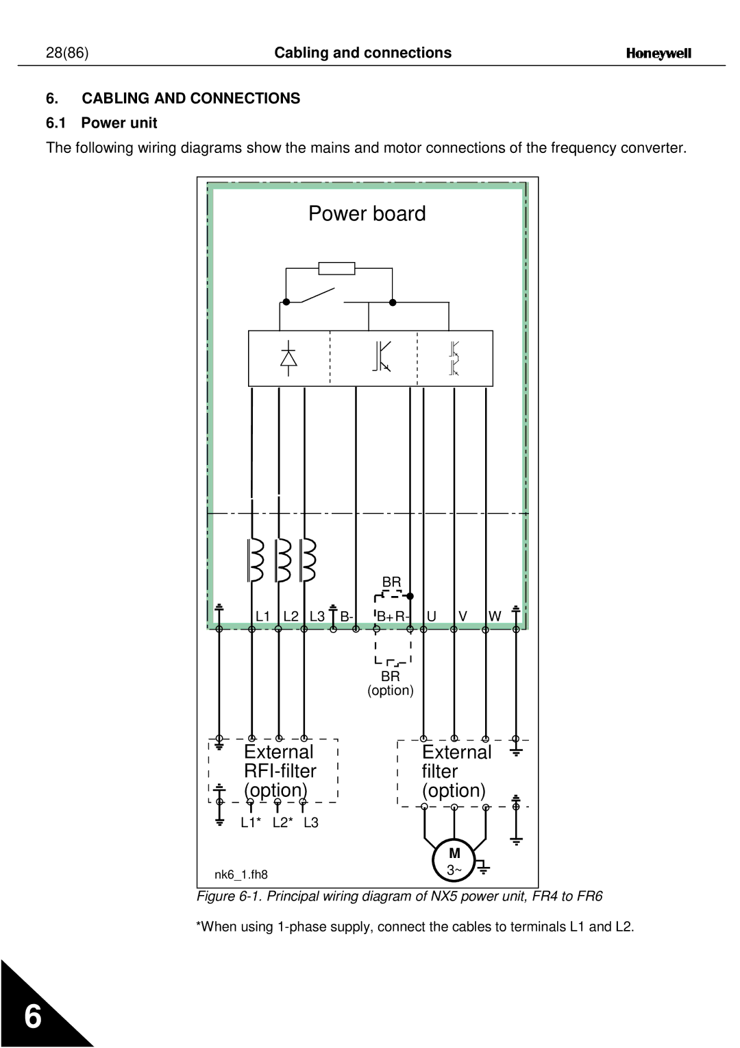
Power unit
Cabling and connections
External RFI-filter Filter Option
2986
Power connections
Mains cable
Motor cable
Control cable
3186
Cable and fuse sizes
Installation instructions
3286
3386
3486
Stripping lengths of motor and mains cables
NX frequency converter frames and installation of cables
3586
3686
NX, FR5. Protection class IP21
3786
NX, FR6. Protection class IP21
3886
10. NX, FR7. Protection class IP21
3986
Cable installation and the UL standards
Cable and motor insulation checks
Control unit
4086
Control connections
NXOPTA1
4186
Control cables
Galvanic isolation barriers
Control terminal signals
4386
Digital input signal inversions
4486
+24V Ground
+24V
Jumper block AI1 mode AI2 mode
4586
4686
Control keypad
Indications on the Keypad display
Drive status indications See control keypad
See .3.4, Active Faults
4786
Control place indications See control keypad
Status LEDs green green red See control keypad
4886
Reset
Keypad push-buttons
Button descriptions
Select
Navigation on the control keypad
No editing
5186
5286
Monitoring menu M1
5386
Parameter menu M2
5486
P1 P18
Keypad control menu M3
Select the keypad as the active control place by keeping
Selection of control place
Control place
Keypad reference
Keypad direction
Fault types
Active faults menu M4
5886
Fault type symbol Meaning
5986
Fault codes
6086
Fault code Possible cause Correcting measures
6186
Fault time data record
6286
Fault history menu M5
6386
6486
System menu M6
6586
Functions in the System menu
Code Function Min Max Unit Default Cust Selections
6686
Application selection
6786
Language selection
System settings
6886
ChangeEnable ChangeDisabl
6986
Connected Not conn
7086
7186
Keypad settings
Example
Keypad settings Default
7286
7386
Parameter copy
7486
20. Storing and loading of parameter sets
7586
Parameter comparison
7686
Information submenu
7786
Counters menu
7886
Trip counters submenu
7986
Expander board menu M7
G1 G2
Auto
8086
Further keypad functions
8186
Commissioning
Commissioning of the frequency converter
8286
8386
Fault tracing
8486
8586
Bulgaria