9
Fault tracing | 85(86) |
|
|
|
|
|
|
|
|
|
| 14 |
| Frequency | Heatsink temperature is over 90° C. | Check the correct amount and flow of | |||
|
|
| converter over |
|
| cooling air. |
|
|
|
|
| temperature | Over temperature warning is issued when | Check the heatsink for dust. | |||
|
|
|
|
| ° | Check the ambient temperature. | ||
|
|
|
| the heatsink temperature exceeds 85 C. | Make sure that the switching frequency | |||
|
|
|
|
|
| |||
|
|
|
|
|
| is not too high in relation to ambient | ||
|
|
|
|
|
| temperature and motor load. | ||
| 15 |
| Motor stalled | Motor stall protection has tripped. | Check motor. |
|
| |
| 16 |
| Motor | Motor overheating has been detected by | Decrease the motor load. |
| ||
|
|
| overtemperature | frequency converter motor temperature | If no motor overload exists, check the |
| ||
|
|
|
| model. Motor is overloaded. | temperature model parameters. |
| ||
| 17 |
| Motor underload | Motor underload protection has tripped. |
|
|
| |
| 22 |
| EEPROM | Parameter save fault |
|
|
| |
| 23 |
| checksum fault | − | faulty operation |
|
|
|
|
|
|
| − | component failure |
|
|
|
| 24 |
| Changed data | Changes may have occurred in the | No special actions required. Take a |
| ||
|
|
| warning | different counter data due to mains | critical attitude to the counter data. |
| ||
|
|
|
| interruption |
|
|
| |
| 25 |
| Microprocessor | − | faulty operation | Reset the fault | and restart. | |
|
|
| watchdog fault | − | component failure | |||
|
|
| Should the fault | |||||
|
|
|
|
|
| nearest distributor. |
|
|
| 32 |
| Fan cooling | Cooling fan of the frequency converter | Contact your nearest distributor. | |||
|
|
|
| does not start, when ON command is |
|
|
| |
|
|
|
| given |
|
|
| |
| 34 |
| CAN bus | Sent message not acknowledged. | Ensure that there is another device on | |||
|
|
| communication |
|
| the bus with the same configuration. | ||
| 36 |
| Control unit | NXS Control Unit can not control NXP | Change control units |
|
| |
|
|
|
| Power Unit and vice versa |
|
|
| |
| 37 |
| Device change | Option board changed. | Reset |
|
| |
|
|
|
| Different power rating of drive. |
|
|
| |
| 38 |
| Device added | Option board added. | Reset |
|
| |
|
|
|
| Drive of different power rating added. |
|
|
| |
| 39 |
| Device removed | Option board removed. | Reset |
|
| |
|
|
|
| Drive removed. |
|
|
| |
| 40 |
| Device unknown | Unknown option board or drive. |
|
|
| |
| 41 |
| IGBT temperature | IGBT Inverter Bridge overtemperature | Check loading. |
|
| |
|
|
|
| protection has detected too high a short | Check motor size. |
|
| |
|
|
|
| term overload current |
|
|
| |
| 42 |
| Brake resistor | Brake resistor overtemperature protection | Set the deceleration time longer. |
| ||
|
|
| overtemperature | has detected too heavy braking | Use external brake resistor. |
| ||
| 43 |
| Encoder fault | Note the exceptional Fault data record. | Check encoder channel connections. |
| ||
|
|
|
| See 7.3.4.3. Additional codes: | Check the encoder board. |
| ||
|
|
|
| 1 = Encoder 1 channel A is missing |
|
|
| |
|
|
|
| 2 = Encoder 1 channel B is missing |
|
|
| |
|
|
|
| 3 = Both encoder 1 channels are missing |
|
|
| |
|
|
|
| 4 = Encoder reversed |
|
|
| |
| 50 |
| Analogue input | Current at the analogue input is < 4mA. | Check the current loop circuitry. |
| ||
|
|
| Iin < 4mA | − control cable is broken or loose |
|
|
| |
|
|
| (selected signal | − signal source has failed |
|
|
| |
|
|
| range 4 to 20 |
|
|
|
|
|
|
|
| mA) |
|
|
|
|
|
| 51 |
| External fault | Digital input fault. |
|
|
| |
| 52 |
| Keypad | The connection between the control | Check keypad connection and possible | |||
|
|
| communication | keypad and the frequency converter is | keypad cable. |
|
| |
|
|
| fault | broken. |
|
|
| |
|
|
|
|
|
|
|
|
|
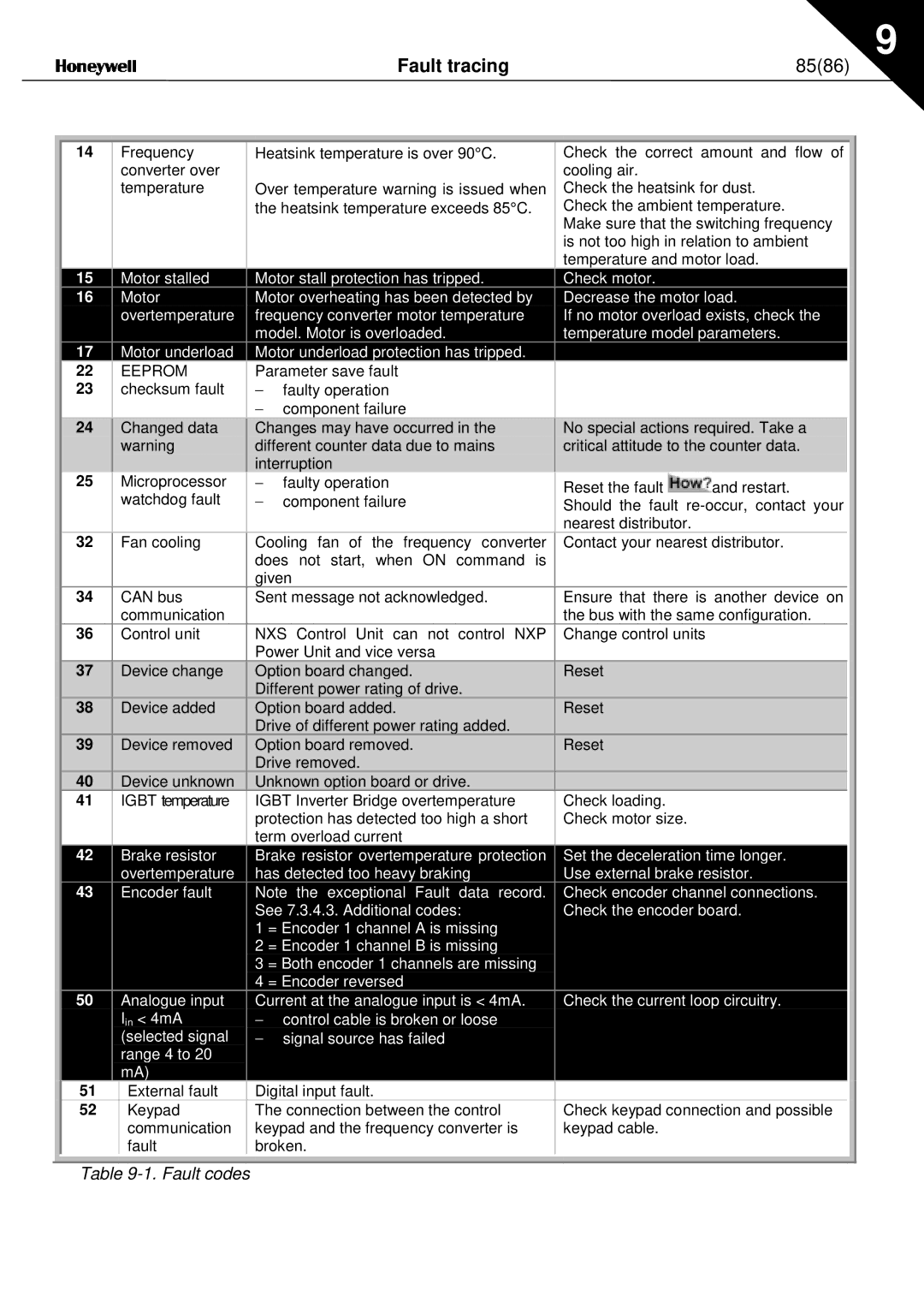
Table
