| LJ4 |
| LJ5 |
LJ6 | LJ7 |
LJ2 | LJ1 |
| |
LJ3 | |
Figure | |
LJ8 |
LJ9 |
LJ1 |
LJ2 |
LJ3 |
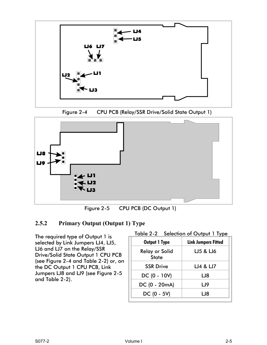
Figure 2-5 CPU PCB (DC Output 1)
2.5.2Primary Output (Output 1) Type
The required type of Output 1 is selected by Link Jumpers LJ4, LJ5, LJ6 and LJ7 on the Relay/SSR Drive/Solid State Output 1 CPU PCB (see Figure
Table
| Output 1 Type | Link Jumpers Fitted |
|
|
|
|
|
| Relay or Solid | LJ5 & LJ6 |
|
| State |
|
|
|
|
|
|
| SSR Drive | LJ4 & LJ7 |
|
|
|
|
|
| DC (0 - 10V) | LJ8 |
|
|
|
|
|
| DC (0 - 20mA) | LJ9 |
|
|
|
|
|
| DC (0 - 5V) | LJ8 |
|
|
|
|
|
|
|
|
|
|
|
|
|
Volume I |