REMOVAL | REPLACEMENT |
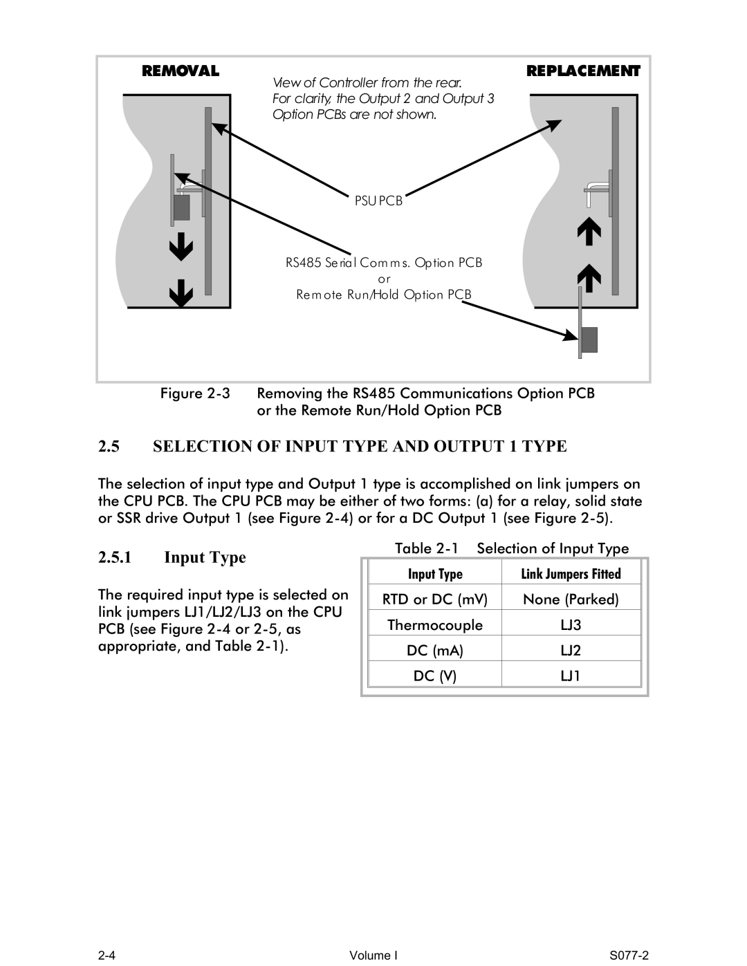
| View of Controller from the rear. |
| For clarity, the Output 2 and Output 3 |
| Option PCBs are not shown. |
| PSU PCB |
| RS485 Se ria l Com m s. Op tion PCB |
| or |
| Re m ote Run/Hold Op tion PCB |
Figure 2-3 Removing the RS485 Communications Option PCB
or the Remote Run/Hold Option PCB
2.5SELECTION OF INPUT TYPE AND OUTPUT 1 TYPE
The selection of input type and Output 1 type is accomplished on link jumpers on the CPU PCB. The CPU PCB may be either of two forms: (a) for a relay, solid state or SSR drive Output 1 (see Figure
2.5.1Input Type
The required input type is selected on link jumpers LJ1/LJ2/LJ3 on the CPU PCB (see Figure
Table
| Input Type | Link Jumpers Fitted |
|
|
|
|
|
| RTD or DC (mV) | None (Parked) |
|
|
|
|
|
| Thermocouple | LJ3 |
|
|
|
|
|
| DC (mA) | LJ2 |
|
|
|
|
|
| DC (V) | LJ1 |
|
|
|
|
|
|
|
|
|
|
|
|
|
Volume I |