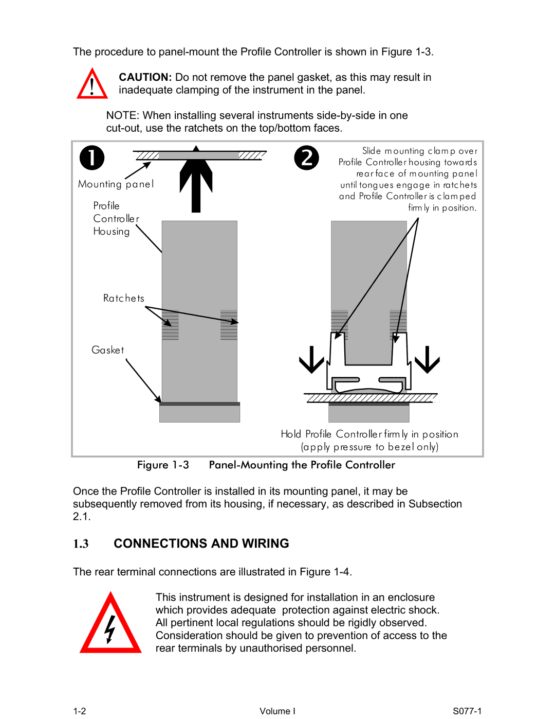
The procedure to
CAUTION: Do not remove the panel gasket, as this may result in inadequate clamping of the instrument in the panel.
NOTE: When installing several instruments
|
|
|
|
|
|
|
| Slid e m ounting c la m p ove r | |
|
|
|
|
|
|
| |||
|
|
|
|
|
|
|
| Profile Controlle r housing towa rd s | |
|
|
|
|
|
|
| |||
|
|
|
|
|
|
|
| re a r fa c e of m ounting p a ne l | |
Mounting p a ne l |
| until tong ue s e ng a g e in ra tc he ts | |||||||
Profile |
| a nd Profile Controlle r is c la m p e d | |||||||
|
| firm ly in p osition. | |||||||
Controlle r |
|
|
|
|
| ||||
|
|
|
| ||||||
Housing |
|
|
| ||||||
Ra tc he ts
Ga ske t
Hold Profile Controlle r firm ly in p osition
(a p p ly p re ssure to b e ze l only)
Figure 1-3 Panel-Mounting the Profile Controller
Once the Profile Controller is installed in its mounting panel, it may be subsequently removed from its housing, if necessary, as described in Subsection 2.1.
1.3CONNECTIONS AND WIRING
The rear terminal connections are illustrated in Figure
This instrument is designed for installation in an enclosure which provides adequate protection against electric shock. All pertinent local regulations should be rigidly observed. Consideration should be given to prevention of access to the rear terminals by unauthorised personnel.
Volume I |