APPENDIX B SUMMARY OF DISPLAYS
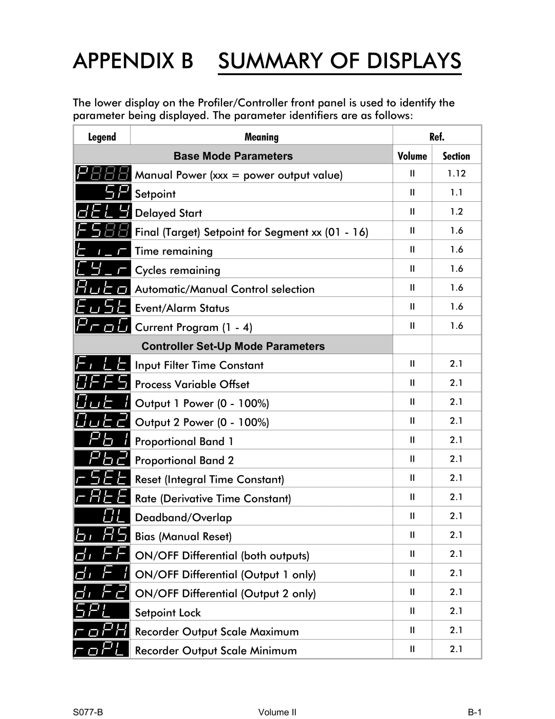
The lower display on the Profiler/Controller front panel is used to identify the parameter being displayed. The parameter identifiers are as follows:
Legend | Meaning |
| Ref. |
| Base Mode Parameters | Volume | Section |
| Manual Power (xxx = power output value) | II | 1.12 |
| Setpoint | II | 1.1 |
| Delayed Start | II | 1.2 |
| Final (Target) Setpoint for Segment xx (01 - 16) | II | 1.6 |
| Time remaining | II | 1.6 |
| Cycles remaining | II | 1.6 |
| Automatic/Manual Control selection | II | 1.6 |
| Event/Alarm Status | II | 1.6 |
| Current Program (1 - 4) | II | 1.6 |
| Controller |
|
|
| Input Filter Time Constant | II | 2.1 |
| Process Variable Offset | II | 2.1 |
| Output 1 Power (0 - 100%) | II | 2.1 |
| Output 2 Power (0 - 100%) | II | 2.1 |
| Proportional Band 1 | II | 2.1 |
| Proportional Band 2 | II | 2.1 |
| Reset (Integral Time Constant) | II | 2.1 |
| Rate (Derivative Time Constant) | II | 2.1 |
| Deadband/Overlap | II | 2.1 |
| Bias (Manual Reset) | II | 2.1 |
| ON/OFF Differential (both outputs) | II | 2.1 |
| ON/OFF Differential (Output 1 only) | II | 2.1 |
| ON/OFF Differential (Output 2 only) | II | 2.1 |
| Setpoint Lock | II | 2.1 |
| Recorder Output Scale Maximum | II | 2.1 |
| Recorder Output Scale Minimum | II | 2.1 |
Volume II |
|