END PANEL LAYOUTS |
|
|
|
| ||||
HCCA25001 & HCCA50001 |
|
|
|
|
| Figure 1 | ||
1 | 2 |
| 3 | 4 | 5 | 7 | 6 | Figura 1 |
| Abbildung 1 | |||||||
ESP |
|
|
|
|
|
|
|
|
|
|
|
|
|
| SYNK REMOTE |
| |
| L | R | L | R |
|
| GAIN |
|
|
|
|
|
| ||||
| INPUT | INPUT OUTPUT | OUTPUT |
|
|
|
| |
|
|
|
| L CH | R CH |
|
|
|
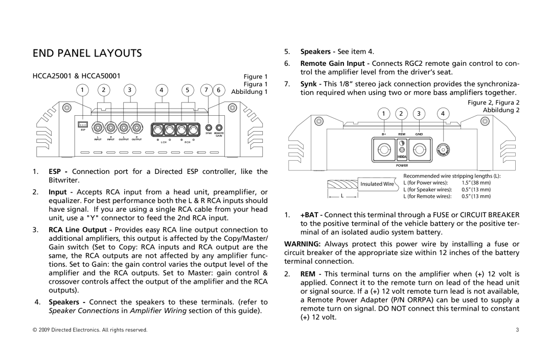
1.ESP - Connection port for a Directed ESP controller, like the Bitwriter.
2.Input - Accepts RCA input from a head unit, preamplifier, or equalizer. For best performance both the L & R RCA inputs should have signal. If you are using a single RCA cable from your head unit, use a "Y" connector to feed the 2nd RCA input.
3.RCA Line Output - Provides easy RCA line output connection to additional amplifiers, this output is affected by the Copy/Master/ Gain switch (Set to Copy: RCA inputs and RCA output are the same, the RCA outputs are not affected by any amplifier func- tions. Set to Gain: the gain control varies the output level of the amplifier and the RCA outputs. Set to Master: gain control & crossover controls affect the output of the amplifier and the RCA outputs).
4.Speakers - Connect the speakers to these terminals. (refer to Speaker Connections in Amplifier Wiring section of this guide).
5.Speakers - See item 4.
6.Remote Gain Input - Connects RGC2 remote gain control to con- trol the amplifier level from the driver’s seat.
7.Synk - This 1/8” stereo jack connection provides the synchroniza- tion required when using two or more bass amplifiers together.
|
|
|
| Figure 2, Figura 2 |
1 | 2 | 3 | 4 | Abbildung 2 |
| ||||
B+ | REM | GND |
|
|
| POWER |
|
|
|
|
|
|
|
|
| Recommended wire stripping lengths (L): | |
|
|
|
|
| Insulated Wire | L (for Power wires): | 1.5” (38 mm) |
|
|
|
|
| |||
|
|
|
|
|
| L (for Speaker wires): | 0.5” (13 mm) |
|
| L |
|
|
| ||
|
|
|
|
| L (for Remote wires): | 0.5” (13 mm) | |
|
|
|
|
|
|
|
|
1.+BAT - Connect this terminal through a FUSE or CIRCUIT BREAKER to the positive terminal of the vehicle battery or the positive ter- minal of an isolated audio system battery.
WARNING: Always protect this power wire by installing a fuse or circuit breaker of the appropriate size within 12 inches of the battery terminal connection.
2.REM - This terminal turns on the amplifier when (+) 12 volt is applied. Connect it to the remote turn on lead of the head unit or signal source. If a (+) 12 volt remote turn lead is not available, a Remote Power Adapter (P/N ORRPA) can be used to supply a remote turn on signal. DO NOT connect this terminal to constant
(+) 12 volt.
© 2009 Directed Electronics. All rights reserved. | 3 |
