After solving the problem, press the red button again to recover the circuit
CAUTION: Refer servicingo quallfted servlce person- nel to solve the problem
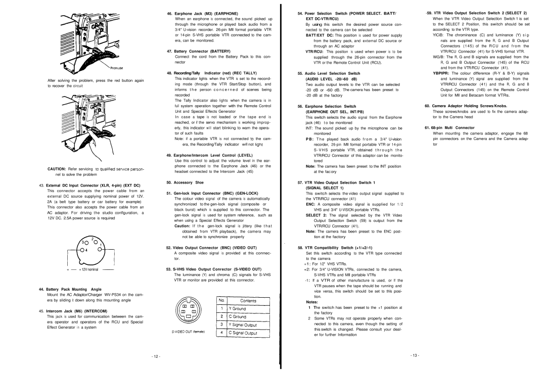
43.External DC Input Connector (XLR,
3 0 ,
4
+- + 12V nominal
44.Battery Pack Mounting Angle
Mount the AC Adaptor/Charger
45.Intercom Jack (M6) (INTERCOM)
This jack is used for communication between the cam- era operator and operators of the RCU and Special Effect Generator in a system
46.Earphone Jack (M3) (EARPHONE)
When an earphone is connected, the sound picked up through the microphone or played back audio from a 3/4"
47.Battery Connector (BATTERY)
Connect the cord from the Battery Pack to this con- nector
48. Recording/Tally Indicator (red) (REC TALLY)
This indicator lights when the VTR is set to the record- ing mode (through the VTR Start/Stop button), and informs t h e person c o n c e r n e d of scenes being recorded
The Tally Indicator also lights when the camera is in full system operation together with the Remote Control Unit and Special Effects Generator
In case a tape is not loaded or the tape end is reached, or if the servo mechanism is working improp- erly, this indicator will start blinking to warn the opera- tor of such faults
Note: if a portable VTR is not connected lo the cam- era, the Recording/Tally indlcator II not light
49. Earphone/Intercom Level Control (LEVEL)
Use this control to adjust the volume level in the ear- phone connected to the Earphone Jack (46) or the headset connected to the Intercom Jack (45)
50.Accessory Shoe
51.Gen-lock Input Connector (BNC) (GEN-LOCK)
The colour video signal of the camera is automatically synchronized to the
Caution: I f t h e
52. Video Output Connector (BNC) (VIDEO OUT)
A composite video signal is provided at this connec- tor.
53.
The luminance (Y) and chroma (C) signals for
- 12 -
54.Power Selection Switch (POWER SELECT. BATT/ EXT DC-VTR/RCU)
By using this switch the desired power source con- nected to the camera can be selected
BATT/EXT DC: This position is used for power supply from the battery pack, and external DC source or through an AC adaptor
VTR/RCU: This position is used when power is to be supplied through the
55.Audio Level Selection Switch
(AUDI0 LEVEL -20/-60 dB)
Two audio output levels to the VTR can be selected
56.Earphone Selection Switch
(EARPHONE OUT SEL, INT/PB)
This switch selects the audio signal from the Earphone jack (46) t o be monitored
INT: The sound picked up by the microphone can be monitored
P B : T h e played back audio f r o m a 3/4"
Note: The camera has been preset to the INT position at the fac:ory
57.VTR Video Output Selection Switch 1
(SIGNAL SELECT 1)
This switch selects the video output signal supplied to the VTR/RCU connector (41)
ENC: A composite video slgnal is supplied for 1 / 2 VHS and 3/4"
SELECT 2: The slgnal selected by the VTR Video Output Selectlon Swtch (59) is output from the VTR/RCU Connector (41).
Note: The camera has been preset to the ENC post- tion at the factory
.
58. VTR Compatibility Switch (+1/+2/-1)
Set thls swltch accordlng to the VTR type connected to the camera
+1: For 1/2" VHS VTRs.
+2: For 3/4"
Notes:
1The switch has been preset to the +1 position at the factory
2Some VTRs may not operate properly when con- nected to this camera, even though the setting of this switch is changed. Please consult your deal- er for further Informatlon
YlCiB: The chrominance (C) and luminance (Y) s i g- nals are supplied from the R, G and B Output Connectors (145) of the RCU and from the VTR/RCU Connector (41) for
WG/B: The R, G and B signals are supplied from the R, G and B Output Connector (145) of the RCU and from the VTR/RCU Connector (41).
YBPIPR: The colour dlfference
60. Camera Adaptor Holding Screws/Knobs.
These screws/knobs are used to fix the camera adap- tor to the Camera head
61. 68-pin Multi Connector
When mountlng the camera adaptor, engage the 68 pin connectors on the Camera and the Camera adap- tor
morw
- 13 -