23.Total pedestal Level Control (T. PED)
This control is used tor adjusting the pedestal level of the video signal (luminance) When attempting to match the pedestal level ot two or more cameras in a
system, use a waveform monitor or oscilloscope for precise adjustment.
24. Audio Level Control (AUDlO)
Only when the MII tormat VTR
25.Check Button (CHECK)
The operating conditions ot the camera can be dis- played in t h e viewfinder b y keeplng this button pressed Reter to page 67 tor details
29.High Gain Selectlon Switch (GAIN LOW/MID/HIGH) This switch is used to select the gain level.
The gain level can be set in the Sub Menu with the combination shown below.
HIGH | MID | LOW |
18dB | 9 dB | 0 dB |
24 dB | 12dB | 0 dB |
12dB | 6dB | 0 dB |
6 dB | 3dB | 0 dB |
12dB | 0 dB | |
6 dB | 0 dB | - 6 d B |
Be sure to use the Operation Seat tor
35.Viewfinder Height Adjustment Knob (UP/DOWN) The height ot the viewfinder can be adjusted by first loosening this knob, adjusting the viewfinder to the proper height, and then tightening this knob Adjustment of up to 20 mm (13/16’) is possible
36.Monitor Output Connector (MONITOR)
A composite video signal tor monitoring is provided at this connector
Note: This output signal might differ slightly trom the output signal ot the Video Output Connector (52)
37. Remote Control Box Connector (RCB)
This connector is provided tor the Remote Control Box (RCB) connection
Note: When connecting the BNC Cable to the Monitor Output Connecter (36). the video signal trom this connector through the Remote Control Box can not be output.
36.Power Indicator
This Indicator lights red when the camera is operating When the camera is in the standby mode, the indica- tor lights green.
CHECK
SHTR BATT AUTO
H.G.
26. Power Switch (DC POWER, OFF/SAVE/ON)
This switch selects the operating mode ot the camera Refer to OPERATING PROCEDURE FOR CAMERA RECORDER APPLICATION on page 45 for details
27.Colour Bar/Night Eye/Camera Selection Switch
(BAR/N.E/CAMERA)
BAR: Set this position to display the colour bars
N.E.: Set this position to shoot the object in the dark scene (Night Eye mode).
The High Gain Selectlon Switch (29) can not work in this mode
CAMERA: By selecting this position,
be set by the High Gain Selection Switch (29)
26. White Balance Selection Switch
30.Lens Hold Ring/Knob
Tum this ring/knob clokwise to secure the lens to the camera
31.Filter Selection Wheel
This wheel, which has four positions, controls two
(1)3200K - indoor light (tungsten, halogen, quartz lamps)
(2)5600K +6 25% ND daylight (sunny)
(3)5600K daylight (cloudy/rainy)
(4)Close
Select the position according to the light source (see page 56)
Caution: if the incorrect filter is selected, the Automatic White Balance Setting may not be suc- cessfully completed
32. Viewfinder Lock Lever |
|
The wiewfinder’s position is locked or released through | |
the use ot this lever When the lever | is released, the |
viwefinder can be slid approximately | 45 mm |
laterally and 20 mm (13/16") back and forth. Be sure | |
to lock the lever after having adjusted the viewfinder | |
position |
|
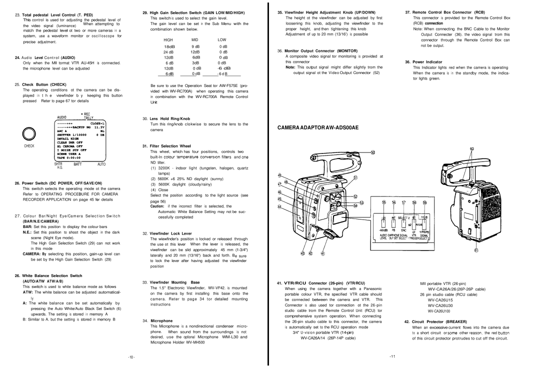
CAMERA ADAPTOR AW-ADS00AE
(AUTO/ATW ATW/A/B)
This switch is used to white balance mode as follows ATW: The white balance can be adjusted automatical-
ly
A:The white balance can be set automatically by pressing the Auto White/Auto Black Set Switch (6) upwards. The setting is stored in memory A
B:Similar to A. but the setting is stored in memory B
33. | Viewfinder Mounting Base |
| The 1.5" Electronic Viewfinder, |
| on the camera by first installing this base onto the |
| camera. Reter to page 34 tor detailed mounting |
| instructions |
34. | Microphone |
| This Microphone is a nondirectional condenser micro- |
| phone. When sound from the surroundings is not |
| desired, use the optional Microphone |
| Microphone Holder |
41. VTR/RCU Connector (26-pin) (VTR/RCU)
When using the camera together with a Panasonic portable colour VTR, the specified VTR cable should be connected between the camera and VTR. This Connector is also used tor connection ot the
3/4"
MII portable VTR
26 pin studio cable (RCU cable)
42.Circuit Protector (BREAKER)
When an excessive current flows into the camera due to a short circuit or some other ieason. the red button of this circuit protector protrudes to cut off the circuit.