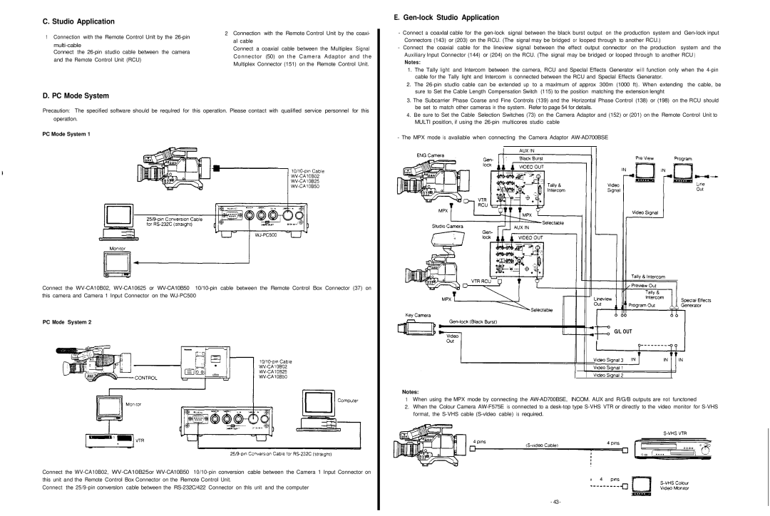
C. Studio Application
1 Connection with the Remote Control Unlt by the | 2 Connection with the Remote Control Unit by the coaxi- | |
al cable | ||
Connect a coaxial cable between the Multiplex Signal | ||
Connect the | ||
Connector (50) on the Camera Adaptor and the | ||
and the Remote Control Unit (RCU) | ||
Multiplex Connector (151) on the Remote Control Unit. | ||
|
D. PC Mode System
Precaution: The specified software should be requlred for this operatlon. Please contact with qualifled service personnel for this operatlon.
PC Mode System 1
Connect the
PC Mode System 2
Connect the
Connect the
E. Gen-lock Studio Application
-Connect a coaxlal cable for the
Connectors (143) or (203) on the RCU. (The signal may be bridged or looped through to another RCU.)
-Connect the coaxial cable for the lineview signal between the effect output connector on the production system and the Auxiliary Input Connector (144) or (204) on the RCU. (The signal may be bridged or looped through to another RCU )
Notes:
1.The Tally light and Intercom between the camera, RCU and Speclal Effects Generator will function only when the
2. The
3.The Subcarrier Phase Coarse and Fine Controls (139) and the Horizontal Phase Control (138) or (198) on the RCU should be set to match other cameras in the system. Refer to page 54 for details. lo etalls.
4. Be sure to Set the Cable Selection Switches (73) on the Camera Adaptor and (152) or (201) on the Remote Control Unit to MULTI positlon, if using the
- The MPX mode is avaliable when connecting the Camera Adaptor
G/L OUT
Notes:
1When using the MPX mode by connecting the
2.When the Colour Camera
- 43-