1.5” ELECTRONIC VIEWFINDER WV-VF42
101. Tally Light
This light is lit when the Tally ON/OFF switch (105) is
set to ON position and the VTR has been set to the recording mode with the VTR Start/Stop Switch. This light indicates that recording in in progress.
102. Accesory Shoe
DO not mount a light source
103.Eye Cap
The eye cap, besides blocking out stray light, offers comfortable viewing of the monitor picture. The cap
may be flipped open if thls is desired.
104. Diopter Adjustment Ring
Rotate this rlng for optimum diopter setting
Note: Loosen the Lock Ring (110) before this adlust- ment
105. Tally ON/OFF Switch (TALLY ON/OFF)
This swtich turns ON/OFF the Tally Light (101) located on front of fhe viewfinder
LED Indicators in the Electronic Viewfinder
- Recording/Tally Indicator (Red)
This indicator lights when the VTR is set to the recording mode by pressing the VTR Start/Stop Switch. When using the camera with a 3/4"
Nota: If a portable VTR is not connect- ed to the camera, the Recording/ Tally Indlcator will not Iight.
When the shutter isturned on, this Iights in green.This indicator Iights yellow to indicate the shutter on when the high gain selection of MID or HIGH has been selected.
And also this indicator lights yellow to indIcate the shutter on when the high gain selection of N E has been selected by the Colour Bar/Night Eye/Camera Selectlon Switch (27).
106. Brightness Control (BRIGHT)
Turn this control clockwise to increase the brightness of the picture in the wiewfinder.
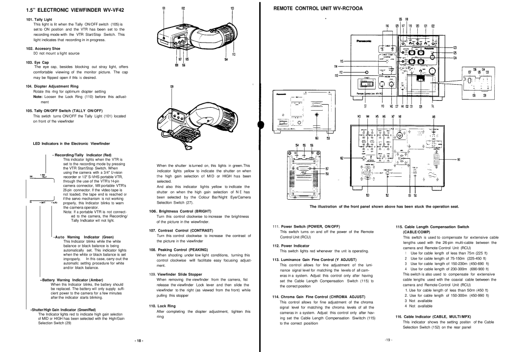
REMOTE CONTROL UNIT WV-RC7OOA
$1 | YO | !k |
The illustration of the front panel shown above has been stuck the operation seat.
improperly. In this case, carry out the automatlc settlng procedure for white and/or black balance.
-Battery Warning Indicator (Amber)
When this lndicator blinks, the battery should be replaced. The battery will only supply suffi- cient power to the camera for a few minutes after the indicator starts blinking.
-Shutter/High Gain Indicator (GreenlRed)
The Indicator lights red to indicate high gain selection of MID or HIGH has been selected with the High/Gain Selection Switch (29)
107. Contrast Control (CONTRAST)
Turn this control clockwise to increase the contrast of the picture in the viewfinder
108. Peaking Control (PEAKING)
When shooting under low light conditions, turning this control clockwise will facilitate easy focusing adjust- ment.
109.Viewfinder Slide Stopper
When removing the viewfinder from the camera, fist release the viewfinder Lock lever and then slide the viewfinder to the right (as viewed from the front) while pulling this stopper
110. Lock Ring
After completing the diopter adjustment, tighten this ring
111.Power Switch (POWER, ON/OFF)
Thls swltch turns on and off the power of the Remote Control Unit (RCU)
112. Power Indicator
This switch Iights red whenever the unit is operating.
113. Luminance Gain Fine Control (Y ADJUST)
This control allows for fine adjustment of the lumi- nance signal level for matching the levels of all cam- eras in a system. Adjust this control only after having set the Cable Length Compensation Switch (115) to the correct position
114. Chroma Gain Fine Control (CHROMA ADJUST)
This control allows for fine adjustment of the chroma signal level for matching the chroma levels of all the cameras in a system. Adjust this control only after hav- ing set the Cable Length Compensation Switch (115) to the correct position
115.Cable Length Compensation Switch (CABLE/COMP)
This swltch is used to compensate for extensive cable lengths used with the
1Use for cable length of less than 75m (225 ft)
2 Use for cable length of
3 Use for cable length of
4Use for cable length of
1.Use for cable length of less than 50m (450 ft)
2.Use for cable length of
3Not avallable
4Not avallable
116.Cable Indicator (CABLE, MULTI/MPX)
Thls indicator shows the setting position of the Cable Selection Switch (152) on the rear panel
- 18 -