Important Information
Identifications of caution marks
License Agreement
Article 1 Grant of License
Article 2 Copyrights
Name of Software Copyright Owners
Handle the liquid crystal display LCD with care
Liquid crystal display and viewfinder
Hold the DVD Video Camera correctly
Do not subject the DVD Video Camera to impact
Be careful of ambient temperature
Do not use a generally available 8 cm CD lens cleaner
Heat on surface of product
Screen on connected TV
Be careful of moisture condensation
This could cause malfunctions
Recorded contents cannot be compensated for
Suggestions and Restrictions
Make a trial recording
Copyright
Read This First
Quick Index
Quick index for the information you use most often this
126
Notation of cancel button
About This Manual
Displays in this manual
2and 3 marks beside headings
Introduction
You can record even during playback
You can immediately play back desired recorded scenes
Use Disc Navigation to create your original movie
Create original DVDs on PC
Table of Contents
Advanced Techniques
Disc Navigation
Installing Software
Subsidiary Information
Checking Provided Accessories
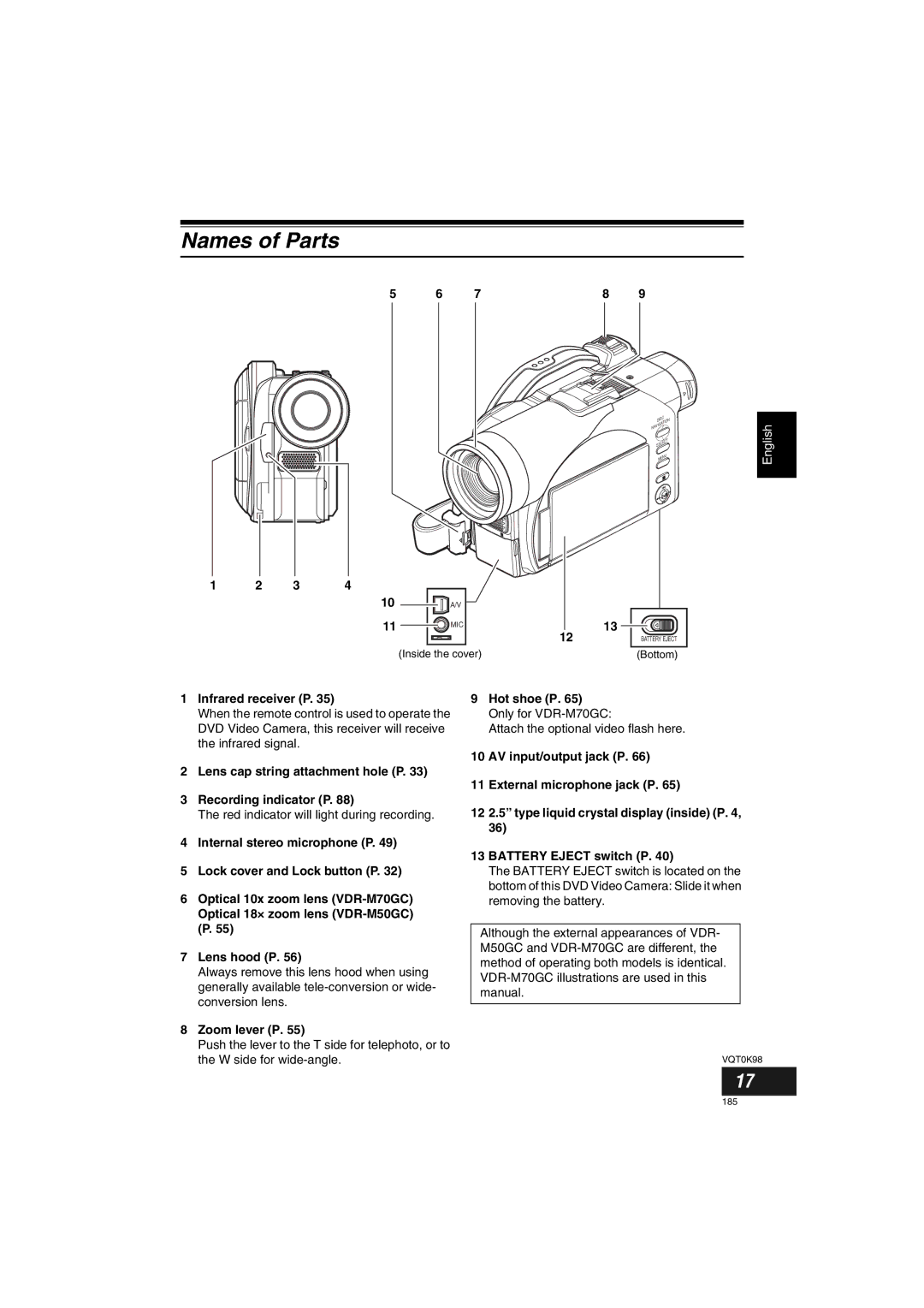
Lens cap string attachment hole P Recording indicator P
Names of Parts
Infrared receiver P
Zoom lever P
ACCESS/PC indicator P , 49
Viewfinder P Dioptre control P
Disc Eject lever P
Press and release this lever to open the disc guide
Reset button P
Stop/cancel button P , 57
3233
Full Auto button P
188
Setting Up the Battery
Charging Battery
Battery charged status
Use the provided AC adaptor/charger to charge the battery
You can delete the recorded contents See
Try to Record and Play Back Using Disc Video and Photo
Connect a power supply P
Start recording P Open the LCD monitor See
Try to Record and Play Back Using Card Photo
Only photos can be recorded on card
REC button
Discs and Cards
Available Discs
Information on DVD-R Disc
Finalising DVD-R disc
Handling Discs Using discs
Storing discs
Removing and Replacing from/in Round DVD Holder
Disc or if it is warped,
Handling card
Available Cards
Common cautions for disc and card
Storage Capacity on Disc or Card
Recordable Time of Movie Video
Image quality prioritized
Recording time prioritized
Recordable Stills Photos on Card
Size and Quality of Photos
For VDR-M50GC
For VDR-M70GC
Setting Up the DVD Video Camera
Holding DVD Video Camera
To use as a Grip Belt
To use as a Hand Strap
Attaching Lens Cap
Attaching Shoulder Strap
To use as a Grip Belt again
Removing Battery from Remote Control
Inserting Battery into Remote Control
While pushing the battery stopper, slide the battery out
Using Remote Control
Viewing Subject through Viewfinder
Viewing Image on LCD Monitor Screen
Range where the LCD monitor can Be moved
LCD monitor can be opened up to
Closing LCD Monitor
205
Date Setup and then
Press the Menu button
Menu screen will
Appear
Changing Display Format of Date and Time
Display format Example of display
Attaching Battery to DVD Video Camera
About the Battery Pack
Removing Battery
Time taken for charging Battery pack is as follows at 25C
Without any extraordinary operation, such as zooming
Places
165 min
Battery Remaining Level Indicator
Efficient Use of Battery
Using DVD Video Camera with AC adaptor/charger
Inserting and Removing Disc
Inserting Disc
Identifying recording/playback sides of disc
Single sided disc
When recording on this DVD Video Camera
When using brand-new DVD-R disc
When recording data from PC
Removing Disc
Inserting and Removing Card
Removing Card
Close the cover of card insertion block
Insert card with its terminal inward until it locks
Basic Handling of DVD Video Camera
Turning DVD Video Camera On and Off
Set to
Set to OFF
Recording Movie
Recording Stills
Press the Back Light button during recording
Compensating for Backlight
Backlight correction icon will appear
On-Screen Information
Recording mode
Information Display During Recording
Highest quality only when using DVD-RAM disc
High quality
Number of recordable stills is
Prioritised
Switching the information display mode
Display when recording an image of yourself
Zooming
Macro Recording
Playing Back
Before You Begin
Playing Back
Turn the DVD Video Camera on P
Search Playback of Movie
Playback from Start of Disc or Card
Frame Advance/Frame Back/Slow Playback of Movie
When using disc
When using card
Skip Playback of Movie
Playing Back Stills
Jumping to specified Point Go To
Specifying the point to view
On-Screen Information Display
Information Display during Playback
Focusing During Recording
Manually Focusing Subject
Focusing range
Adjusting Exposure Manually
Using Full Auto Function
Following settings will reset to defaults
Function
Focus
Using External Microphone
Setting Video Flash Only for VDR-M70GC
Setting On-screen Manner
Emitting light
Connecting to a TV
Viewing on TV Screen
Viewing on TV Screen
Perform playback, recording or editing
Playback on DVD Video Recorder/Player
Request when recording to hard disk of DVD video recorder
To Customers who Have a DVD Video Recorder with Hard Disk
Playback on DVD Player
No further data can be recorded on finalised disc
How to Remove Disc
When the Hinge of Round DVD Holder Comes off
Disc Cleaning
Removing and Replacing from/in Round DVD Holder
Recording Dubbing Images
Recording Dubbing Images from Other Video Device
Recording Dubbing Images from Other Video Cameras
Set the input source on DVD Video Camera to
Recording Dubbing Images on Other Video Devices
Interpreting screen for setting
Understanding Flow of Menu
Camera Functions Setup Date Setup
Record Functions Setup
Initial Setup
Flow of Menu
Subject, as in a wedding or on stage
Setting Up Camera Functions
Midsummer or on a ski slope
Adjusting Colour White Bal
Mode Setting content On-screen
Setting white balance manually
Press the Cbutton to end Setting
Button, choose White
Bal., Set, and then
Checking SIS On or Off
Using the Image Stabiliser SIS
Reducing Wind Noise during Recording Wind Cut
Switching to Cinema Mode
Setup screen, and then
Choose Cinema on
Camera Functions
Setting Up Record Functions
Switching Movie Quality Video Mode
Switching Quality of Still Image Quality
Choose the option you want, and then press Button
Switching External Input Recording Method Photo Input
Setting Contents
Recording Details of setting
Receiving Image from Another Device Input Source
Self-Timer
Setting On-Screen Display Output On or Off OSD Output
Choose On or Off, and press the Abutton
LCD Setup
Setting Brightness of LCD Screen Brightness
Setting Colour Density of LCD Screen Colour Level
Colour density adjustment bar will appear on the screen
Initial Settings
Switching Operating Sound On or Off Beep
Turning DVD Video Camera Off Automatically Power Save
Choose Power Save on Initial Setup menu
Changing Display Language Language
Turning Record LED On or Off Record LED
Off
Resetting Menu Settings to Defaults Reset
Choose Reset on Initial Setup menu
Setting items have now been reset to defaults
Joystick to choose YES Then press the a
Using Disc Navigation
Starting Disc Navigation
Play
When playback ends
Playing Back from Disc Navigation Screen
Selecting Multiple Scenes
Selecting Consecutive Scenes Together
Cursor Bar graph Status of scenes
Blue
Disc Navigation Menu
Available function Disc or card used Contents Reference
Functions Available with Disc Navigation
When using DVD-RAM disc
When using DVD-R disc
When using card
Understanding Flow of Disc Navigation Menu
Scene
Deleting Scenes Delete
Editing using submenu
To move the cursor to the first scene
Changing Images for Thumbnails Edit Thumbnail
Appear Choose YES
Then press the a Button
Press the Cbutton to quit
Playing Back by Skipping Scenes Edit Skip
Releasing Skip
Arranging Order of Scenes Edit Move
Appear If you are sure
100
Adding Special Effects Edit Fade
Fade screen will
For in and/or OUT
101
Combining Multiple Scenes Edit Combine
Combine and then press
Combine Scenes
102
Dividing Movies Edit Divide
Set the power switch to Press the Disc Navigation button
103
Copying Stills on DVD-RAM Disc to Card Copy
Press the Menu button Choose Copy on
Locking Scenes on Card Lock
104
To unlock the scene
105
Designating Scenes to Be Printed Dpof
Use joystick to specify
Number of prints,
Selecting Scenes Using Menu Screen Select
106
Deselecting selected scenes
Deselecting scenes one by one
Displaying Information Using Menu Screen Detail
107
What is programme?
Switching to Thumbnail Display of Specific Date Switch
Programme
108
109
Playing Back Programme Play
Changing Title of Programme Title
Program menu screen Then press the a
110
Characters available for entering title
After entering the title
Choose Enter and then
What is play list?
Play List
111
Creating New Play List Create
112
Switching to Display of Each Play List Switch
Editing on play list
113
Playing Back a Play List Play
114
Adding Scenes to Play List Editing Play List
Choose Edit on
Press the Cbutton The screen for verifying exit will appear
115
Adding Scenes Using Submenu for Editing Editing Play List
Deleting Scenes from Play List Editing Play List
Deleting Scenes Using Submenu for Editing Editing Play List
116
Current → End, All on
Select menu screen
117
Arranging Order of Scenes Move
Move will appear
Move
Changing Title of Play List Title
118
Deleting Play List Delete
119
Go To
Top End
Disc or Card Management
120
Verifying Remaining Free Space on Disc or Card Capacity
Protecting Disc from Writing Protect Disc
121
Initialising DVD-RAM Disc or Card Format Disc/Format Card
Recorded on disc or card may be damaged
Press the Disc Navigation button Press the Menu button
Then the Disc Navigation menu screen Will be restored
122
Message for
Proceeding will appear
Finalising DVD-R Disc Finalize Disc
123
Result, and at worst, the disc may be damaged
Others
124
125
Slide Show Continuous Playback of Stills
Choose Slide Show
All or DPOF, and then
126
Contents on Provided CD-ROM
128
DVD-MovieAlbumSEMyDVD
Installing USB Driver
USB Driver Installation button
129
Then use the provided USB cable to
Operation with DVD Video Camera connected
130
Click Finish
Installing DVD-RAM Driver Before Installing DVD-RAM Driver
131
132
Click Next
133
134
Installing DVD-MovieAlbumSE
Choose the TV broadcast system Ntsc or PAL, click Next
Installation will start
Check the contents, and then click Next
135
Screen for installing MyDVD will appear Click Next
Installing MyDVD
136
137
Click Finish, and then restart the PC
Europe London
Phone
138
Click the Start button to start export
139
Recordable time on
Uninstalling Software
Uninstalling USB Driver
140
With Windows 98 Second Edition/Me
141
Deleting Other Applications
Cleaning LCD screen and camera lens
Cleaning
142
Before Requesting Service
143
Check 5 No DVD Video Camera operation
144
Check 6 No image in viewfinder
Trouble Messages
Message Cause & Troubleshooting Reference
145
146
147
148
149
150
151
152
Troubleshooting
Power supplies
Symptom Cause and Correction Reference
153
Adjust the dioptre control
154
During recording
Then set it to Again
Clean the disc Poor playback picture
155
During playback
Button will not start Camera? Playback
Photos on card cannot
156
Number of pixels will take some time to appear
When the DVD Video Camera is connected to PC
157
158
159
Miscellaneous
System Reset
List of setting items
Default Setting
160
Major Specifications
USB 2.0 compliant Hi-Speed Recording mode Movie with sound
VDR-M70GC approx in Fine mode
161
162
Dimensions W × H × D 61 W × 32 H × 91 D mm Weight Approx g
163
Introduction to Optional Accessory
164
Information on Square Adaptor
Removing disc from square adaptor
Terminology
165
166
167
168
169
170
171
VQT0K98