■Connection with the Extension Units
●SCSI Connection
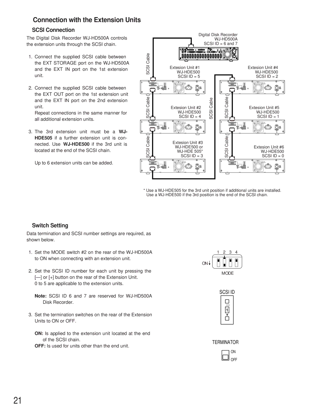
The Digital Disk Recorder
1. Connect the supplied SCSI cable between |
the EXT STORAGE port on the |
Cable
Digital Disk Recorder
SCSI ID = 6 and 7
IN |
| EXT STORAGE |
|
|
| COPY |
|
|
| SIGNAL GND |
|
| ||||
SPOT |
|
|
|
|
|
|
|
|
| DATA |
| 10/100 |
| AC | ||
OUT |
|
|
|
|
|
|
|
|
|
| SERIAL |
|
| IN | ||
OUT |
|
| CONTROL |
|
| ALARM |
|
| MODE |
|
|
|
|
|
|
|
MULTI SCREEN OUT AUDIO | 14 | 12 | 11 | 9 | 8 | 6 | 5 | 4 | 3 | 2 | 1 |
| ||||
16 | 15 | 13 | 10 | 7 |
| |||||||||||
IN |
|
|
|
|
|
|
|
|
|
|
|
|
|
|
|
|
OUT |
|
|
|
|
|
|
|
|
|
|
|
|
|
|
|
|
16 | 15 | 14 | 13 | 12 | 11 | 10 | 9 | 8 | 7 | 6 | 5 | 4 | 3 | 2 | 1 | POWER |
|
|
|
|
|
|
| VIDEO |
|
|
|
|
|
|
|
| |
and the EXT IN port on the 1st extension |
unit. |
2. Connect the supplied SCSI cable between |
the EXT OUT port on the 1st extension unit |
and the EXT IN port on the 2nd extension |
unit. |
Repeat connections in the same manner for |
all additional extension units. |
3. The 3rd extension unit must be a WJ-
SCSI
EXT IN |
EXT OUT |
|
|
|
| GND | NC |
SCSI ID |
|
| |||
|
| TERMINATOR |
| ||
SCSI Cable![]()
EXT IN |
EXT OUT |
|
|
|
| GND | NC |
SCSI ID |
|
| |||
|
| TERMINATOR |
| ||
Extesion Unit #1
AC IN | POWER |
| ON |
| OFF |
| SIGNAL GND |
Extesion Unit #2
AC IN | POWER |
| ON |
| OFF |
| SIGNAL GND |
SCSI Cable
EXT IN |
EXT OUT |
|
|
|
| GND | NC |
SCSI ID |
|
| |||
|
| TERMINATOR |
| ||
SCSI Cable![]()
EXT IN |
EXT OUT |
|
|
|
| GND | NC |
SCSI ID |
|
| |||
|
| TERMINATOR |
| ||
Extesion Unit #4
AC IN | POWER |
| ON |
| OFF |
| SIGNAL GND |
Extesion Unit #5
AC IN | POWER |
| ON |
| OFF |
| SIGNAL GND |
HDE505 if a further extension unit is con- nected. Use
Up to 6 extension units can be added.
CableSCSI![]()
EXT IN
EXT OUT
|
|
|
|
| GND | NC |
SCSI ID |
|
|
| |||
|
| TERMINATOR |
| |||
|
|
|
|
|
|
|
Extesion Unit #3
AC IN | POWER |
| ON |
| OFF |
| SIGNAL GND |
Cable |
| Extesion Unit #6 |
SCSI |
| |
| SCSI ID = 0 | |
|
|
|
EXT IN |
|
|
EXT OUT |
|
|
| GND NC | AC INPOWER |
SCSI ID | ON | |
| TERMINATOR | OFF |
SIGNAL GND
*Use a
●Switch Setting
Data termination and SCSI number settings are required, as shown below.
1.Set the MODE switch #2 on the rear of the
2.Set the SCSI ID number for each unit by pressing the
[–]or [+] button on the rear of the Extension Unit. 0 to 5 are applicable to the extension units.
Note: SCSI ID 6 and 7 are reserved for
3.Set the termination switches on the rear of the Extension Units to ON or OFF.
ON: Is applied to the extension unit located at the end of the SCSI chain.
OFF: Is used for units other than the end unit.
1 2 3 4
ON ![]()
MODE
SCSI ID
–
1
+
TERMINATOR
ON
![]() OFF
OFF
21