■Connection with the DVD Extension Unit
The
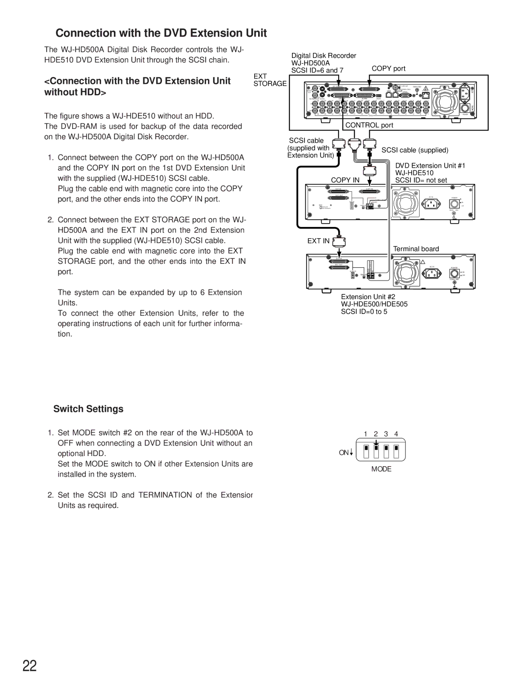
<Connection with the DVD Extension Unit without HDD>
The figure shows a WJ-HDE510 without an HDD.
The DVD-RAM is used for backup of the data recorded on the WJ-HD500A Digital Disk Recorder.
1.Connect between the COPY port on the WJ-HD500A and the COPY IN port on the 1st DVD Extension Unit with the supplied (WJ-HDE510) SCSI cable.
Plug the cable end with magnetic core into the COPY port, and the other ends into the COPY IN port.
2.Connect between the EXT STORAGE port on the WJ- HD500A and the EXT IN port on the 2nd Extension Unit with the supplied (WJ-HDE510) SCSI cable.
Plug the cable end with magnetic core into the EXT STORAGE port, and the other ends into the EXT IN port.
Digital Disk Recorder |
|
COPY port | |
SCSI ID=6 and 7 |
EXT |
|
|
|
|
|
|
|
|
|
|
|
|
|
|
|
|
|
STORAGE | IN |
| EXT STORAGE |
|
|
| COPY |
|
|
| SIGNAL GND |
|
| ||||
| SPOT |
|
|
|
|
|
|
|
|
| DATA |
|
| AC | |||
|
|
|
|
|
|
|
|
|
|
| SERIAL |
|
| ||||
| OUT |
|
|
|
|
|
|
|
|
|
|
|
|
|
| IN | |
| OUT |
|
| CONTROL |
|
| ALARM |
| MODE |
|
|
|
|
|
|
|
|
| MULTI SCREEN OUT AUDIO | 14 | 12 | 11 | 9 | 7 | 6 | 5 | 4 | 3 | 2 | 1 |
| ||||
| 16 | 15 | 13 | 10 | 8 |
| |||||||||||
| IN |
|
|
|
|
|
|
|
|
|
|
|
|
|
|
|
|
|
|
|
|
|
|
|
|
|
|
|
|
|
|
|
|
| ON |
|
|
|
|
|
|
|
|
|
|
|
|
|
|
|
|
| OFF |
| OUT |
|
|
|
|
|
|
|
|
|
|
|
|
|
|
|
|
| 16 | 15 | 14 | 13 | 12 | 11 | 10 | 9 | 8 | 7 | 6 | 5 | 4 | 3 | 2 | 1 | POWER |
|
|
|
|
|
|
|
| VIDEO |
|
|
|
|
|
|
|
|
|
|
|
|
|
| CONTROL port |
|
|
|
|
|
| ||||||
SCSI cable |
| |
(supplied with | SCSI cable (supplied) | |
Extension Unit) | ||
|
|
|
|
| DVD Extension Unit #1 | |
| COPY IN |
|
|
|
|
|
|
| SCSI ID= not set |
| |
| EXT IN | COPY IN |
|
| |
| EXT OUT |
|
| AC IN |
|
|
|
| G | POWER | |
| SCSI ID |
| THERMAL ERROR OUT |
|
|
|
| NC |
| ON | |
HDD | - | TERMINATOR |
|
| OFF |
INSTALLED | + | ON |
|
| |
NOT INSTALLED |
| OFF |
|
|
|
|
|
|
|
| SIGNAL GND |
EXT IN |
|
|
| Terminal board |
|
|
|
|
|
| |
| EXT IN |
|
|
|
|
|
| OUT |
|
|
|
| EXT OUT | ERROR |
|
|
|
|
|
| AC IN | POWER | |
| SCSI ID | GND THERMAL | NC |
| ON |
| – | TERMINATOR |
|
| OFF |
| + | ON |
|
| |
|
| OFF |
|
|
|
SIGNAL GND
The system can be expanded by up to 6 Extension Units.
To connect the other Extension Units, refer to the operating instructions of each unit for further informa- tion.
Extension Unit #2
●Switch Settings
1.Set MODE switch #2 on the rear of the
Set the MODE switch to ON if other Extension Units are installed in the system.
2.Set the SCSI ID and TERMINATION of the Extension Units as required.
1 2 3 4
ON ![]()
MODE
22