■Installing the Optional Network Board
The Network Board
1.Unplug the power cord from the
2.Remove the top cover of the Disk Recorder by remov- ing the 11 screws, as shown in the figure.
Disk Recorder
3.Remove the small plate covering the
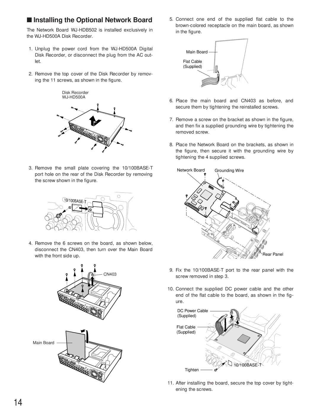
4.Remove the 6 screws on the board, as shown below, disconnect the CN403, then turn over the Main Board with the front side up.
![]()
![]() CN403
CN403
Main Board
5.Connect one end of the supplied flat cable to the
Main Board
Flat Cable (Supplied)
6.Place the main board and CN403 as before, and secure them by tightening the reinstalled screws.
7.Remove a screw on the bracket as shown in the figure, and then fix a supplied grounding wire by tightening the removed screw.
8.Place the Network Board on the brackets, as shown in the figure, then secure it with the grounding wire by tightening the 4 supplied screws.
Network Board | Grounding Wire |
Rear Panel
9.Fix the
10.Connect the supplied DC power cable and the other end of the flat cable to the board, as shown in the fig- ure.
DC Power Cable (Supplied)
Flat Cable ![]() (Supplied)
(Supplied) ![]()
![]()
![]()
![]()
![]()
Tighten ![]()
![]()
11.After installing the board, secure the top cover by tight- ening the screws.
14