@9Direction Buttons (CDA B)
These buttons are used to select an area for a zoomed image displayed on the Multiscreen Monitor.
During the setup, these buttons are used to move the cursor position in the setup menu of the Disk Recorder.
C: Downward
D: Upward
A: Left
B: Right
#0Full Indicator (FULL)
Lights to indicate when the available recording space of the Disk Recorder (HDD) is running low.
#1Hard Disk Drive Indicator (HDD)
Lights to indicate when the Hard Disk is activated.
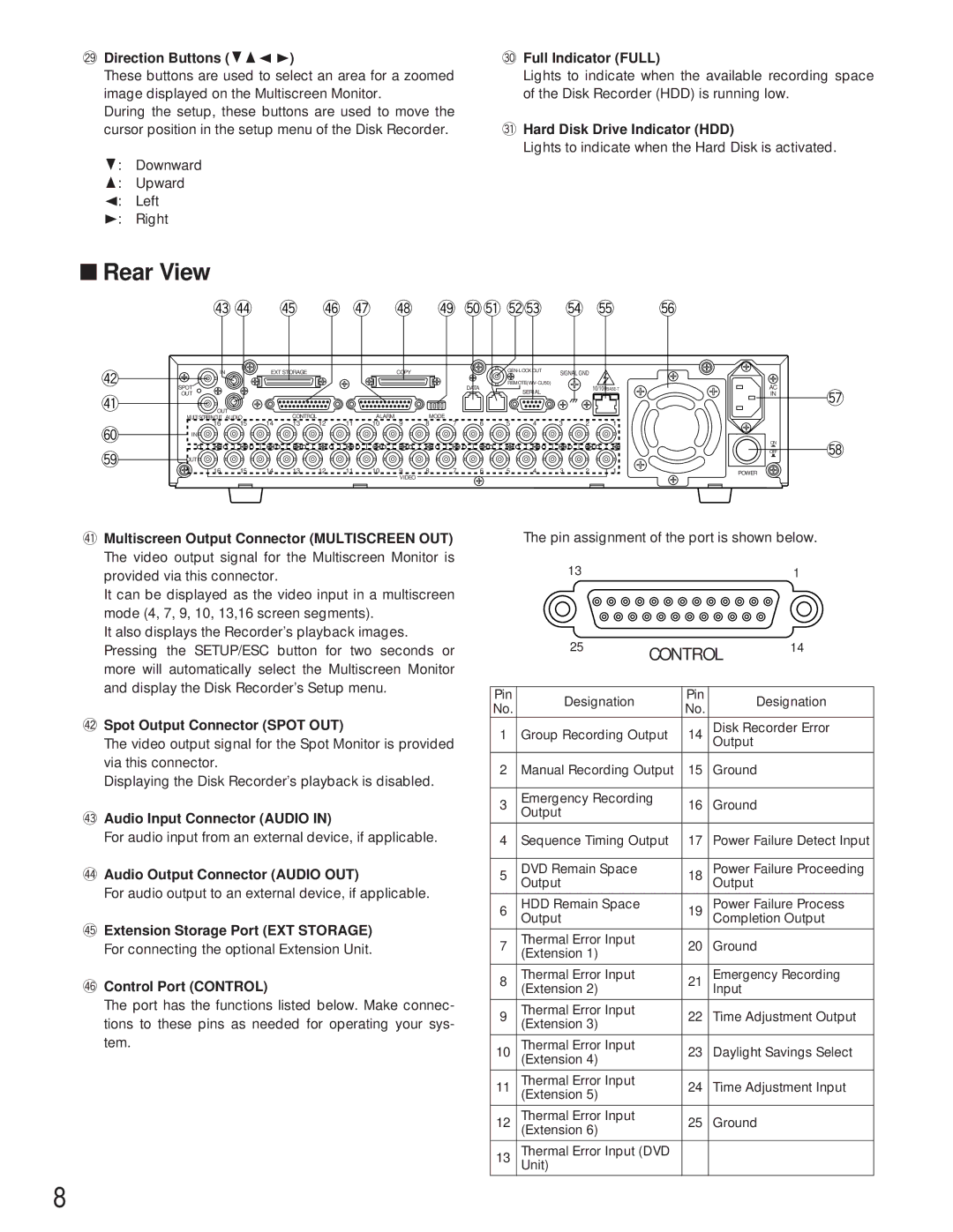
■Rear View
$3$4 | $5 | $6$7 | $8 | $9%0%1%2%3 %4%5 %6 |
$2 $1
^0
%9
IN |
| EXT STORAGE |
|
|
| COPY |
|
|
| SIGNAL GND |
| ||||
SPOT |
|
|
|
|
|
|
|
|
| DATA |
|
| |||
|
|
|
|
|
|
|
|
|
| SERIAL |
|
| |||
OUT |
|
|
|
|
|
|
|
|
|
|
|
|
|
| |
OUT |
|
| CONTROL |
|
| ALARM |
| MODE |
|
|
|
|
|
|
|
MULTI SCREEN OUT AUDIO | 14 | 12 | 11 | 9 | 7 | 6 | 5 | 4 | 3 | 2 | 1 | ||||
16 | 15 | 13 | 10 | 8 | |||||||||||
IN |
|
|
|
|
|
|
|
|
|
|
|
|
|
|
|
OUT |
|
|
|
|
|
|
|
|
|
|
|
|
|
|
|
16 | 15 | 14 | 13 | 12 | 11 | 10 | 9 | 8 | 7 | 6 | 5 | 4 | 3 | 2 | 1 |
|
|
|
|
|
|
| VIDEO |
|
|
|
|
|
|
|
|
AC
IN
ON
OFF
POWER
%7
%8
$1Multiscreen Output Connector (MULTISCREEN OUT)
The video output signal for the Multiscreen Monitor is provided via this connector.
It can be displayed as the video input in a multiscreen mode (4, 7, 9, 10, 13,16 screen segments).
It also displays the Recorder’s playback images. Pressing the SETUP/ESC button for two seconds or more will automatically select the Multiscreen Monitor and display the Disk Recorder’s Setup menu.
$2Spot Output Connector (SPOT OUT)
The video output signal for the Spot Monitor is provided via this connector.
Displaying the Disk Recorder’s playback is disabled.
$3Audio Input Connector (AUDIO IN)
For audio input from an external device, if applicable.
$4Audio Output Connector (AUDIO OUT)
For audio output to an external device, if applicable.
$5Extension Storage Port (EXT STORAGE)
For connecting the optional Extension Unit.
$6Control Port (CONTROL)
The port has the functions listed below. Make connec- tions to these pins as needed for operating your sys- tem.
The pin assignment of the port is shown below.
13 | 1 |
| 25 | CONTROL | 14 | ||
|
|
| |||
|
|
|
|
|
|
Pin | Designation |
| Pin | Designation | |
No. |
| No. | |||
|
|
|
| ||
1 | Group Recording Output | 14 | Disk Recorder Error | ||
Output |
| ||||
|
|
|
|
| |
2 | Manual Recording Output | 15 | Ground |
| |
|
|
|
|
| |
3 | Emergency Recording | 16 | Ground |
| |
Output |
|
| |||
|
|
|
|
| |
|
|
|
| ||
4 | Sequence Timing Output | 17 | Power Failure Detect Input | ||
|
|
|
|
| |
5 | DVD Remain Space |
| 18 | Power Failure Proceeding | |
Output |
| Output |
| ||
|
|
|
|
| |
6 | HDD Remain Space |
| 19 | Power Failure Process | |
Output |
| Completion Output | |||
|
|
|
|
|
|
7 | Thermal Error Input |
| 20 | Ground |
|
(Extension 1) |
|
| |||
|
|
|
|
| |
|
|
|
|
| |
8 | Thermal Error Input |
| 21 | Emergency Recording | |
(Extension 2) |
| Input |
| ||
|
|
|
|
|
|
9 | Thermal Error Input |
| 22 | Time Adjustment Output | |
(Extension 3) |
| ||||
|
|
|
|
| |
|
|
|
|
|
|
10 | Thermal Error Input |
| 23 | Daylight Savings Select | |
(Extension 4) |
| ||||
|
|
|
|
|
|
11 | Thermal Error Input |
| 24 | Time Adjustment Input | |
(Extension 5) |
| ||||
|
|
|
|
|
|
12 | Thermal Error Input |
| 25 | Ground |
|
(Extension 6) |
|
| |||
|
|
|
|
| |
13 | Thermal Error Input (DVD |
|
|
| |
Unit) |
|
|
|
| |
|
|
|
|
|
|
8