Paradise Datacom LLC
Wheaton Road 1012 E. Boal Avenue
Table of Contents
Change, Tx/Rx, Mod/Demod, REED-SOLOMON Menu
Change, Tx/Rx, Mod/Demod, Scrambler Menu
Change, Tx/Rx, ESC/Aux/BA, Define IDR Menu
100
Page
Page
Page
EMC Electromagnetic Compatibility and Safety Notices
Safety
EMC
Electromagnetic Compatibility
Installation
Environmental
Introduction
Overview
P300 Series Features
Requires Drop/Insert feature standard on P300 IBS and above
Feature Summary
Feature Means h/w option
Feature Highlight
Fault and a deferred alarm
Wideband if Feature
High Date Rate Feature
IBS/SMS Feature
Drop/Insert Feature
P300 / P310 -IDR Additional Features IDR Option
Prbs tester feature
P300 / P310 -TCM Additional Features
Extended D/I Feature
`Custom Features` Feature
Turbo Product Code Forward Error Correction TPC FEC
Fault Philosophy
Description
Operation
Electrical Description
Front Panel Features
P300 Modem front panel view
Keyboard
Normal operation there should be three Green LEDsshowing
Rear Panel Description
Rating
Tx if output
Async ESC connector
Rx if input
Services
Terrestrial Interface Connectors
Overhead Pinout details are provided in Appendix B
Standby LED
Block Diagram
To FEC/Modulator FromFEC/Demodulator
Match
Summary of Specifications
Common Main Specifications
Channel Spacing Phase and Amplitude
OutputOutput FrequencyPhase NoiseStability
Scrambling
Filter Implementation
Demodulator Specifications
8PSK/TCM
Clocking and Buffering
Intelsat Reed Solomon Codec & Custom Features
Framing & Deframing
Async ESC Feature & Aux Data Channel
Drop /Insert Feature
Extended Drop/ Insert Feature
IDR Option
Traffic Log
Prbs Tester Feature
Monitor/AGC Option
Auto Uplink Power Control Aupc
Common Specifications
Configuration Memories
Redundancy Features
Weight
Controller
Power Supply
Safety
Supporting Products
EMC
P300H P300 Series Modem Installation and Operating Handbook
P300H P300 Series Modem Installation and Operating Handbook
P300H P300 Series Modem Installation and Operating Handbook
8PSK
P300H P300 Series Modem Installation and Operating Handbook
Installation and Configuration
Menu System
Introduction
Menu Structure Diagrams
To Completely Setup Initially
Menu Structure Sheet 1 / 7 Main Status, Change
Full Menu Structure Sheet 2 / 7 Main Monitor, Info
P300H P300 Series Modem Installation and Operating Handbook
P300H P300 Series Modem Installation and Operating Handbook
Full Menu Structure Sheet 5 / 7 Change, Tx
Full Menu Structure Sheet 6 / 6 Change, Rx
Full Menu Structure Sheet 7 / 7 Change, BUC/LNB
Status Display no faults
Status Screen Display
Carr Fault
Configuration Summary
Carr Disabled
Detailed Receive Traffic Status
Unit Fault Tx if synth failure Tx carrier muted
Traffic Summary Screen
Detailed Transmit Traffic Status
Detailed Demodulator Status
Setup Initial Configuration Menu
Setup 1Initial Config 2Check Memories 3Store 4Recall 5Erase
Tx 1Service 2Baseband 3Clocking 4Modulator 5ESC/Aux/BA
CHANGE, TX Menu
Change, Tx/Rx, Service, Closed Network
Closed Network mode ? =No ESC normal 2 Plus ESC min o/h
No ESC
Plus ESC
Same async ESC rate
Change, Tx/Rx, Service, Closed Net, Plus ESC, BA Menu
Normal
Change, Tx/Rx, Baseband, Continuous Menu
Change, Tx/Rx, Baseband Menu
Tx BB ? 1=Continuous data 2=Drop Mux 3=Other function
Change, Tx/Rx, Baseband, DROP/INSERT Menu
Select bearer ? =G.732 2=T1-D4 3=T1-ESF
Drop TS 1, 3-5, 17-15 Toggle ??-?? YES Help
Change, Tx/Rx, Baseband, Drop/Insert, Timeslot Menu
Dropped TS ? =Leave 2=Replace with idle code
Leave
Replace
=Normal ignore 2=Transfer via sat o/h
T1 RBS over satellite ? =Normal or no RBS 2=Maintain RBS
Change, Tx/Rx, Baseband, Drop/Insert, RBS Menu
Dont Care
=Normal maintain 2=Don’t care
Normal Maintain
TS identity over satellite ? =Maintain 2=Don’t care Normal
Dont
Change, Tx/Rx, Baseband, Other Menu
Audio
Tx clock mode ? =Tx Clock In 2=Internal 3=Rx ref=Sat
Change, Tx, Clocking Menu
TX Clock
Internal
Clock
Change, Tx/Rx, Mod/Demod, if Frequency Menu
Change, Tx/Rx, Modulator, Modulation Menu Set modulation ?
=BPSK 2=QPSK 3=OQPSK 4=8PSK
None, Viterbi or Sequential at rate ½, ¾, or
Offset Qpsk Oqpsk Primer
Is available
Screen Description Exact Delay Code rate Bits
For Turbo FEC the FEC rate selection screen is as follows
Modulation Schemes from
V3.57 V3.40
Change, Tx/Rx, Mod/Demod, REED-SOLOMON Menu
Introduction to REED-SOLOMON
Other
Tx RS outer codec ? =Off 2=INTELSAT n,k,t & depth 3=Other
Intelsat
Performance
Non standard equipment which leads onto the following menus
Toggle Scramblers =IBS Off 2=RS N/A 3=V.35 On 4=Turbo N/A
Change, Tx/Rx, Mod/Demod, Scrambler-Custom Menu
Power Break Mute
Change, Tx, Modulator, Power Level Menu
Set Tx Power -15.3dBm Enter value ??.? YES, or to change
RTS Controlled
Change, Tx, Modulator, Aupc Software =V2.12
Change, Tx, Modulator, Aupc Menu
Change, Tx, Modulator, Aupc Mode Menu Modes are as follows
MON Dist
Monitoring and logging of distant performance
Self MON
Change, Tx, Modulator, AUPC, Tolerance Menu
Maximum
Freeze
Nominal
Change, Tx/Rx, ESC/AUX/BA Menu
IDR 8k ESC ? =Off 2=Sync 3=Async
IDR Mode ESC & AUX Port Definitions
Change, Tx/Rx, ESC/Aux/BA, Define IDR Menu
IBS Mode ESC & AUX Port Definitions
Change, Tx/Rx, ESC/Aux/BA, Define IBS Menu
ESC Port ? =Off 2High Rate async channel
High Rate Async
ALL Avail
Sync Aux circuit o/h usage ? =Maximum 2Custom
Custom
Use 1=TS0b1=XXX 2=TS32b1=XXX =TS32b3=XXX 4=TS32b4=XXX
Custom IBS Overhead Allocation
Use 1=TS16=XXX 2=TS32b5&6=XXX YES =TS32b7&8=XXX 4=TS48=XXX
Change, Tx/Rx, ESC/Aux/BA, Async ESC Menu
Baud Rate
Format
SET AS M&C
Change, Tx/Rx, ESC/Aux/BA, Config Async, Baud Rate Menu
Change, Tx/Rx, ESC/Aux/BA, Config Async, SET AS REM M&C
Change, Tx/Rx, ESC/Aux/BA, Interfaces Menu
Local
Remote
Aux Interface
Change, Tx/Rx, ESC/Aux/BA, Audio Levels89Menu
Change, Tx/Rx, ESC/Aux/BA, Backward Alarms Menu
Eeee
Aeee
Aooo
CHANGE, RX Menu
Change, Rx Menu Rx not set to follow Tx
Change, Rx, Service Menu
Change, Rx, Baseband Menu
Bearer Routing
Insert bearer ? =Loop Terr 2=Generate internally
Sat TS 1-3 Toggle??-?? YES
Change, Rx, Baseband, Insert Mux, Partial, Data Select Menu
Change, Rx, Buffer / Clocking Menu
Change, Rx, Buffer / Clocking, Station Clock Menu
Station clock connection ? 1=None 2Via BNC 3RS422
Station clock frequency 0kHz 10MHz ????? YES
Change, Rx, Buffer / Clocking, RX Clock Menu
Normal non-Insert Mux operation
Satellite
TX CLK
Reference as backup in order to maintain the Rx traffic
Station
Same rate
DCE CLK
Change, Rx, Buffer / Clocking, Buffer Size Menu
Buffer size end-end 16ms 99ms ??ms YES
Change, Rx, DEMOD’ Menu
Rx=Tx Active
Change, Rx, Demod’, if Frequency Menu
Change, Rx, Demod’, Modulation Menu
Exactly on frequency
BPSK, Qpsk & 8PSK
Oqpsk
Change, Rx, Demod’ Aupc Menu
Change, Rx, ESC/AUX/BA Menu
Change, Rx, RX=TX Menu
Set Rx=Tx, so most Rx parameters track Tx ? =Off 2=On
Terr-Interface Nothing to configure With card fitted YES
CHANGE, TERR-INTFC Menu
Terr interface 1Electrical 2Control Lines 3Card specific
Change, Terr-intfc, Electrical
Set G.703 line code ? 1=AMI 2=HDB3 Normal
Set T1 line length ?ft =133 2=266 3=399 4=533 5=655
Interface control lines? =Ignore all 2Active-configure
Line RTS Tx input signal valid ? =Ignore 2=Active
Change, Terr-intfc, Control Lines
Line DTR DTE Ready In ? =Ignore 2=Active
Rem M&C philosophy ? =Takeaway 2Giveaway+M&C Timeout
CHANGE, REM-M&C Menu
Local Control Take Away / Give Away Selection
Takeaway
Address
Protocol
Interface
CHANGE, USER-OPT Menu
Change, User-Opt, Thresholds Menu
User BER
Buffer Slip
Enabled BER Action
Default Action
Backalarm
Buffer Autocentre
Default Auto
Change, User-Opt, Operation, Terrestrial Menu
Bearer CRC
Bits
FAW
FEC
Prbs
IBS MF Period
Back ALM MAP
Change, User-Opt, Operation, TERR/SAT Menu
Buffer MF Slip
Spoof
Status Screen
Upgrade Messages
Change, User-Opt, Display Menu Options are
Now 112935 on 12/06/97 OK yes Time adjust, 2 Date Adjust
Change TIME/DATE Menu
CHANGE, BUC/LNB Menu
BUC/LNB 1Tx/BUC 2Rx/LNB 3Tune Ref
Lower Frequency Limit Upper Frequency Limit Frequency Shift
Change, BUC/LNB, Tx/BUC, BUC Type Menu
BUC Type
Change, BUC/LNB, Tx/BUC, DC & References Menu
Tx/BUC 1DC SupplyOn 210M RefOff 3Current Monitor2400 2800mA
Change, BUC/LNB, Tx/BUC, SHF POWER/UNITS Menu
Change, BUC/LNB, Tx/BUC, SHF Power/Units Menu
Change, BUC/LNB, Tx/BUC, SHF Frequency Menu
Freq shift of upconverter13050 MHz 65535MHz ??.??? YES
BUC
1BUC On/OffOn 2BUC Attenuator7dB Power at BUC reads 32.7dBm
Change, BUC/LNB, Tx/BUC, BUC Control Menu
Low Frequency Limit High Frequency Limit Frequency Shift
Change, BUC/LNB, Rx/LNB, LNB Type Menu
Description
Freq shift of downconverter13050 MHz 65535MHz ??.??? YES
Change, BUC/LNB, Rx/LNB, DC & References Menu
Change, BUC/LNB, Rx/LNB, SHF Frequencies Menu
Change, BUC/LNB, Tune Ref Menu
Tune Reference50% to nudge
Monitor Menu
Monitor, Carrier IDs Menu
Monitor, Carrier IDs Menu
Monitor, Distant Eb/No & BER Menu
Distant end Eb/No=9.7dB Distant end final BER=1.3E-7
Distant Eb/No9.7dB Target10.±0.5dB Delta power+1.5dB
BUC Type Std Ku Modem/BUC Mode Terminal
Monitor, Aupc Menu
Limits +3.5 -1.0dB Slew10dB/min Comms lost actionNominal
BUC Type Std Ku Software ver 2 Power Class 2W = +33dBm
Info Menu
LOG Menu
Aupc Delta Power
Buffer %
Bert BER
TX Terr BER
FEC L
Test Menu
Test 1Loopbacks Off 2RF & FEC Off PSU/Temp 4Int Bert ESC
FRM L
Framer output is also looped
Remote R
Data is not looped back to the remote site
TX CW
RS Corrections
Main, ESC, or Aux channel, restoring normal operation
Main
ESC / AUX
Closed Network
IBS/SMS
IDR
Custom Framing
Manual
Test, Int BERT, Pattern Menu Bert Pattern 1211-12047 2215-1
ONE Minute
Errors
Bert
Loss#
Time
Setup Menu
Slip Count Reset
Action Menu
Buffer Centre
Service Menu
Service 1User Parameters 2Factory parameters
Help Menu
Help 1Emergency Tx Carrier Off 2Menu operation 3Glossary
Range
Traffic for a few seconds
=IBS 2=IDR
Menu Screens for Specialist Options
Custom Framing Menus
MIN O/H
Backward Alarm? =Normal 2=No Backward Alarm facility
Overhead Mode ? =Normal 2=Min o/h to provide set ESC
Change, Tx/Rx, Service, Custom, IDR Menu
LOW
High
IDR o/h ? 1=96k2x16k-Audio+32k-BER =64k2x16k-Audio only
NORMAL96K
1XAUDIO64K
No AUDIO32K
16k Modes
2048K IBS mode ? =Normal 6.7% overhead 2=G.732 0% overhead
IBS/SMS Operation with 2048KBPS Continuous Data
Change, Tx/Rx, Baseband, Continuous, 2048k G.732 Menu IBS
Channel Assoc Sig CAS in TS16 ? =Normal No CAS 2=CAS
Timeslot re-order option ? 1=Normal linear 2=Re-order
TS order 0, 17-31, 16 Toggle ??-?? YES Help
2048k IDR mode ? 1=Normal
Custom IDR Operation with 2048KBPS Continuous Data
Change, Tx/Rx, Baseband, Continuous, 2048k Menu IDR
Frame as per normal IDR operation
Application Notes
Doppler & Plesiochronous Buffering
Determining Clocking Schemes and Buffer Size
Determining Buffer Size
Bs = .002 + 172800 x Ms x Lc + Rc Seconds
Partial Insert and Multidestinational Working
Which the Tx data was dropped
Choosing Optimum Custom Values of RS N&K
Optimum n,k,t
+ FEC
Determining Exact Maximum ESC Baud Rates
Allocated to the ESC
Closed Network Plus ESC
Closed Network Plus ESC via the Custom Service menu
TS32 MF
ESC channel `delayed character mode` very technical
E1CCS 2048kbps G.732 with common Channel Signalling
E1CAS 2048kbps G.732 with Channel Associated Signalling
Cross Reference to SDM300 D/I & Framing Modes
E1IBS 2048kbps with no assumed G.732 frame format
Configure as follows
T1ESF & T1ESFS 1544kbps Extended Super Frame S Special
T1 & T1S 1544kbps D4 Framed S Special
T1IBS 1544kbps in the same bandwidth as Normal 1536kbps IBS
Other Derivatives
V.35 Scramblers
History
1x10⁻⁸error rate Hopeless Data invert and 1x10⁻⁸error rate
1x10⁻⁸error rate Hopeless Data Invert
Hopeless Linkabit Data invert and 1x10⁻⁸error rate
FDC Linkabit Pattern Dependent
Introduction to Aupc Automatic Uplink Power Control
Introduction
Limit only
Eb/No
P300H P300 Series Modem Installation and Operating Handbook
Configuring Aupc for operation
No slew rate limit
Target
Accurately you wish to try and maintain the Eb/No
Tutorial on CARRIER/NOISE & Eb/No Measurements Introduction
Derivation of Eb/No from C+N/N
RS Code Rate
12.4 Eb/No Explanatory Diagram
Summary
Adjust for Modulation FEC Rate RS Codec
Tables to Convert C+N/N to Eb/No
Theory
Switching Philosophy
For 1 Operation
Practical 1 for 1 Implementation
Detected failures
Manual changeovers
Boot Code Operation
Flash Software Update
Other Boot Code Options
Banks
Appendix a Data Interface Information General
P1440 in RS422 Mode
Data Circuit Towards Modem TX
P1440 in V.35 Mode
Local Loop Remote Loop
141 140
RS232
P1440 in RS232 Mode
Shield
P1440 in G.703 Mode
Switch/Link Settings
Line Code / Line Length
Sw2 position
P300H P300 Series Modem Installation and Operating Handbook
Clocking Important
P1440 in X.21 Mode
DCE Operation
DTE Operation
113 103 105 104 109 102 101 19, 20 RS422 Ground Screen
MIL-STD-188-114A Interface
With older equipment
P1451 Eurocom D/1 `D` & `G` Plus MULTI-STANDARD Interface
Eurocom D/1 interface `D` operation
Links
All links settings are
Eurocom D/1 interface `G` operation
Pin Signal Name
Direction
Name-RS485 SA Bus Paradise
Name RS232
Interconnecting Devices Using RS485
P200 / P230 / P230DI P1300 / P1301
Connector type 9 Pin `D male
Connector
For 1 Interface
Serial In/Out
Alarms & AGC Connector
Connector type 15 pin `D male
Alarms Connector
Prompt Traffic a Tx or Rx traffic fault exists
Async ESC Connector
Async ESC Connector
RX Constellation Monitor Port
Differential Station Clock
Standard Lead
Serial Port for LOG Printing or Embedded M&C Update
Async Port for ESC or AUX Channels
ESC/AUX & Backward Alarms Connector
Connector type 50 pin `D female
ESC Port
Pin Number Sync Async RS 485 / RS422 usage RS 232 usage
Aux Port
Pin Number Sync Async RS422 usage
Audio Ports
Pin Number Description
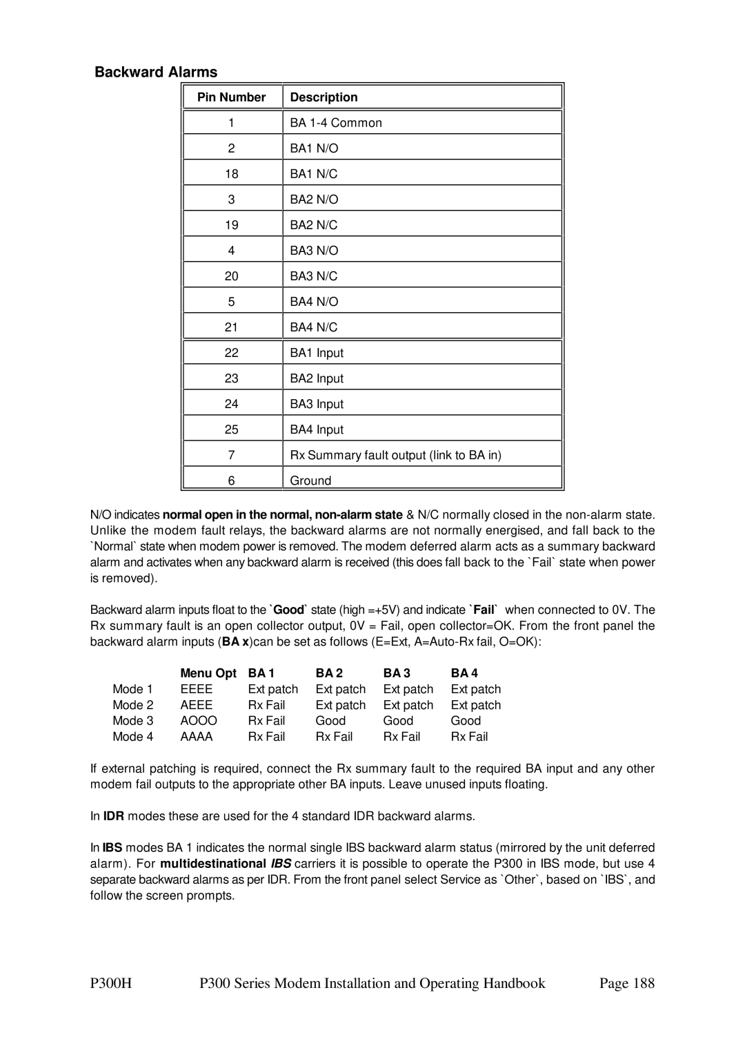
Backward Alarms
Menu Opt
Appendix C Upgrade Information
P300 Series Modem Hardware
Appendix C1 Modem Capabilities & Upgrades
Appendix C2 Feature Screens
Determining the Hardware Capability of a Modem
Hardware
Features in USE
Features in use by current config C E P - S - W X - Read
Features Temporary
Features Hardware
Features Test
Alphabetic Feature List
Letter Description of Feature
Appendix C3 Features on Demo Expire Soon
Appendix C5 Upgrade Available
Appendix C6 Features not Available
Do not Ignore this Message
Appendix D Remote M&C Remote M&C Protocol
Summary
Character Format / Baud Rate
RS 485 `A` Line
Message Structure
Paradise / FDC
Fixed character 02H
`Body`, up to and including the asterisk
SA-bus
Fixed character 06H or 15H
Checksum As Master to Slave
Message Categories
List of All Remote M&C Messages
First Direction Avail
Build Name Filename
Appendix E Customer Specific Features
Relay Mode Setting
Cable & Wireless Alarms Summarise
Tx Carrier On/Off indication Software =V2.12
Fault Mode Setting
Default normal fault detection
Severely Degraded Phase noise mode
Max Sequential decoder gain
Disable the Upper Temperature Limit
Comstream Sequential Mode Software =V2.12
Coarse AGC voltage Rx Signal level, default
Fine AGC voltage Rx Signal level
Uncommitted DAC Output Control
Rx Eb/No Level
Aupc Delta Power Software versions =2.12
Distant end Eb/No Software versions =2.12
IBS/SMS Service Features
Standard Features specified in IBS/SMS definitions
Additional Features Paradise products
Appendix F Framing and DROP/INSERT Overview IBS/SMS Framing
Backward Alarm
TS32 Multiframe
Synchronous IBS Scrambler
Low Rate ESC Channel
P300H P300 Series Modem Installation and Operating Handbook
Signalling Systems Introduction CCS, CAS & RBS
Common Channel Signalling CCS
Channel Associated Signalling
Robbed Bit Signalling RBS
CAS Multiframe
CAS Multiframe Summary
32+ CAS =
IDR Framing
IDR Service Features
Standard Features specified in IDR definitions
Appendix G Fault Messages and Action Table
P300H P300 Series Installation and Operating Handbook
Relays To Terr To Sat Other
Text on Display Description / Cause / Notes
CM, TF
Relays To Terr To Sat
To try and maintain the set flange power
Rx Traffic Faults Rx OK LED Off and Rx Traffic prompt relay
TA,TC
To Sat Other
An open or short circuit
P300H P300 Series Installation and Operating Handbook
P300H P300 Series Installation and Operating Handbook
Actions Relays
P300H P300 Series Installation and Operating Handbook