Chapter 2 - Hardware Installation
Connecting and Setting Up the MGC+100/ MGC+50
To Connect the MGC+100/ MGC+50 to the network and power source and set up the system the following procedures are performed:
•Connecting the MGC+ unit to the power source (AC inlet)
•Connecting the MGC+ unit to the LAN Network
•Connecting the MGC+ unit to the network(s)
Connecting to the Power Source
You can connect to an AC Inlet power supply at your site. It is important to follow these steps.
The following restrictions apply to the conductors and connectors that may be used to ground the unit when rack mounted:
•When using bare conductors, they must be coated with an appropriate antioxidant compound before crimp connections are made. Tinned,
•The same bolt assemblies should not secure multiple connectors.
•Listed fastening hardware must be compatible with the materials being joined and must be preclude loosening, deterioration and electrochemical corrosion of the hardware and joint materials.
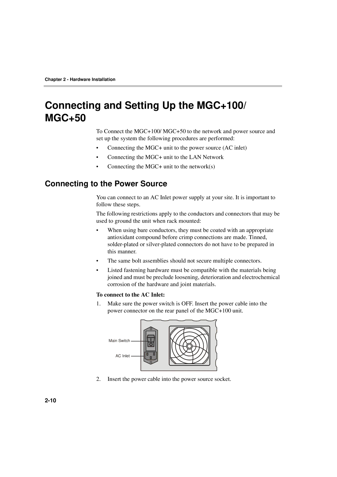
To connect to the AC Inlet:
1.Make sure the power switch is OFF. Insert the power cable into the power connector on the rear panel of the MGC+100 unit.
Main Switch ![]()
![]()
![]()
AC Inlet
2.Insert the power cable into the power source socket.