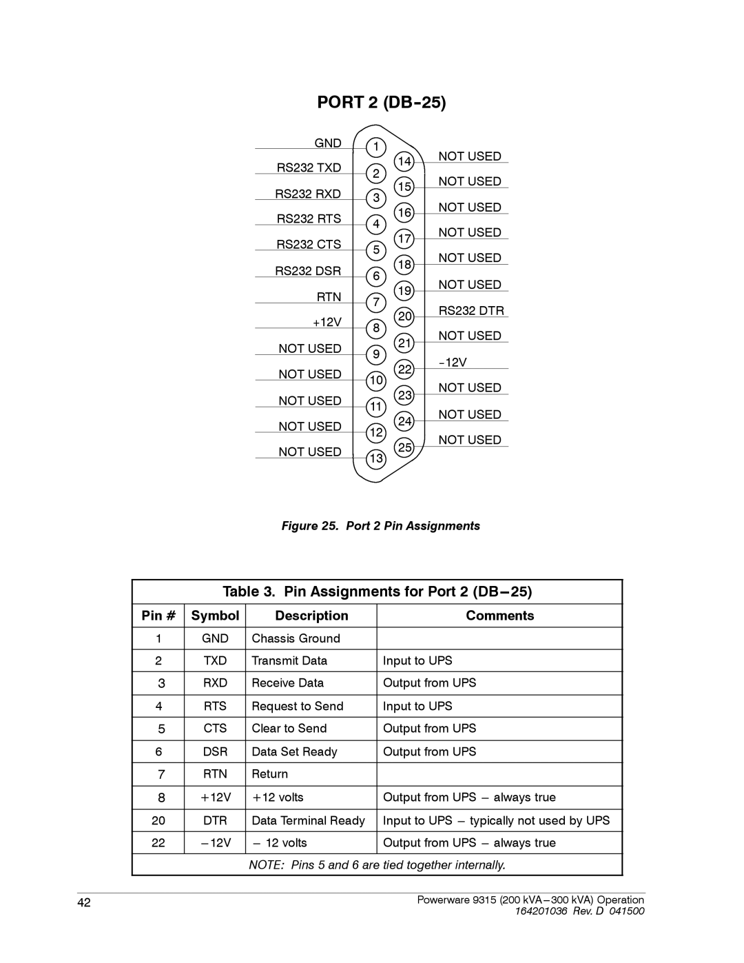
PORT 2 (DB-25)
GND | 1 |
RS232 TXD | 14 | |
2 | ||
| ||
RS232 RXD | 15 | |
3 | ||
| ||
RS232 RTS | 16 | |
4 | ||
| ||
RS232 CTS | 17 | |
5 | ||
| ||
RS232 DSR | 18 | |
6 | ||
| ||
RTN | 19 | |
7 | ||
| ||
+12V | 20 | |
8 | ||
| ||
NOT USED | 21 | |
9 | ||
| ||
NOT USED | 22 | |
10 | ||
| ||
NOT USED | 23 | |
11 | ||
| ||
NOT USED | 24 | |
12 | ||
| ||
NOT USED | 25 | |
13 | ||
|
NOT USED
NOT USED
NOT USED
NOT USED
NOT USED
NOT USED
RS232 DTR
NOT USED
NOT USED
NOT USED
NOT USED
Figure 25. Port 2 Pin Assignments
Table 3. Pin Assignments for Port 2 (DB---25)
Pin # | Symbol | Description | Comments |
|
|
|
|
1 | GND | Chassis Ground |
|
|
|
|
|
2 | TXD | Transmit Data | Input to UPS |
|
|
|
|
3 | RXD | Receive Data | Output from UPS |
|
|
|
|
4 | RTS | Request to Send | Input to UPS |
|
|
|
|
5 | CTS | Clear to Send | Output from UPS |
|
|
|
|
6 | DSR | Data Set Ready | Output from UPS |
|
|
|
|
7 | RTN | Return |
|
|
|
|
|
8 | +12V | +12 volts | Output from UPS |
|
|
|
|
20 | DTR | Data Terminal Ready | Input to UPS |
|
|
|
|
22 | Output from UPS | ||
|
|
|
|
|
| NOTE: Pins 5 and 6 are tied together internally. | |
42 | Powerware 9315 (200 kVA |
| 164201036 Rev. D 041500 |