Summary Alarm Contacts
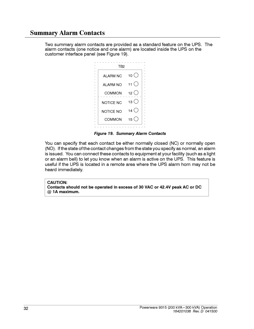
Two summary alarm contacts are provided as a standard feature on the UPS. The alarm contacts (one notice and one alarm) are located inside the UPS on the customer interface panel (see Figure 19).
TB2 |
|
ALARM NC | 10 |
ALARM NO | 11 |
COMMON | 12 |
NOTICE NC | 13 |
NOTICE NO | 14 |
COMMON | 15 |
Figure 19. Summary Alarm Contacts
You can specify that each contact be either normally closed (NC) or normally open (NO). If the state of the contact changes from the state you specify as normal, an alarm is issued. You can connect these contacts to equipment at your facility (such as a light or an alarm bell) to let you know when an alarm is active on the UPS. This feature is useful if the UPS is located in a remote area where the UPS alarm horn may not be heard immediately.
CAUTION:
Contacts should not be operated in excess of 30 VAC or 42.4V peak AC or DC @ 1A maximum.
32 | Powerware 9315 (200 kVA |
| 164201036 Rev. D 041500 |