A

2 – General Description Serial Port

2.4

Serial Port

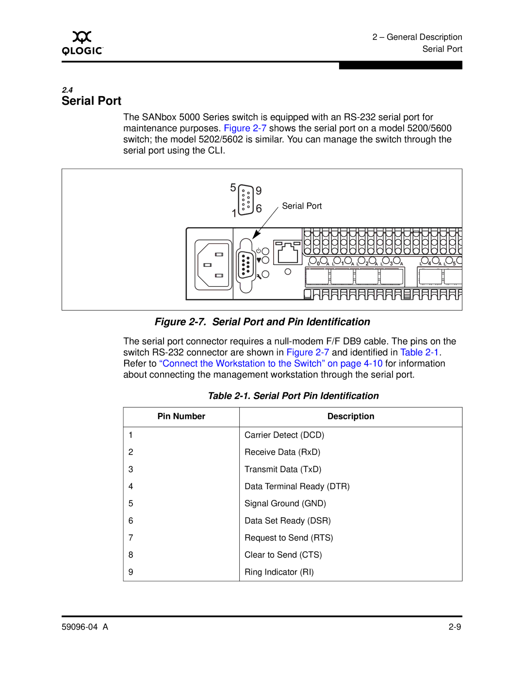
The SANbox 5000 Series switch is equipped with an RS-232 serial port for maintenance purposes. Figure 2-7shows the serial port on a model 5200/5600 switch; the model 5202/5602 is similar. You can manage the switch through the serial port using the CLI.

Serial Port


L 0 A L 1 A L 2 A L 3 A

L 4 A L 5

Figure 2-7. Serial Port and Pin Identification

The serial port connector requires a null-modem F/F DB9 cable. The pins on the switch RS-232 connector are shown in Figure 2-7and identified in Table 2-1. Refer to “Connect the Workstation to the Switch” on page 4-10for information about connecting the management workstation through the serial port.


Table 2-1. Serial Port Pin Identification


Pin Number


Description


1


Carrier Detect (DCD)

2


Receive Data (RxD)

3


Transmit Data (TxD)

4


Data Terminal Ready (DTR)

5


Signal Ground (GND)

6


Data Set Ready (DSR)

7


Request to Send (RTS)

8


Clear to Send (CTS)

9


Ring Indicator (RI)


59096-04 A

2-9

Page 35
Image 35
Q-Logic 5000 manual Serial Port Pin Identification