4 – Installation Installing a Switch
WARNING!! If the switch is mounted in a closed or multi-rack assembly, the operating temperature of the rack environment may be greater than the ambient temperature. Be sure to install the chassis in an environment that is compatible with the maximum rated ambient temperature. Refer to “Environmental” on page A-5for technical specifications.
Do not restrict chassis air flow. Allow 16 cm (6.5 in) minimum clearance at the front and rear of the switch (surface mount) or rack for service access and ventilation.
Multiple rack-mounted units connected to the AC supply circuit may overload that circuit or overload the AC supply wiring. Consider the power source capacity and the total power usage of all switches on the circuit. Refer to “Electrical” on page A-5.
Reliable grounding in the rack must be maintained from the switch chassis to the AC power source.
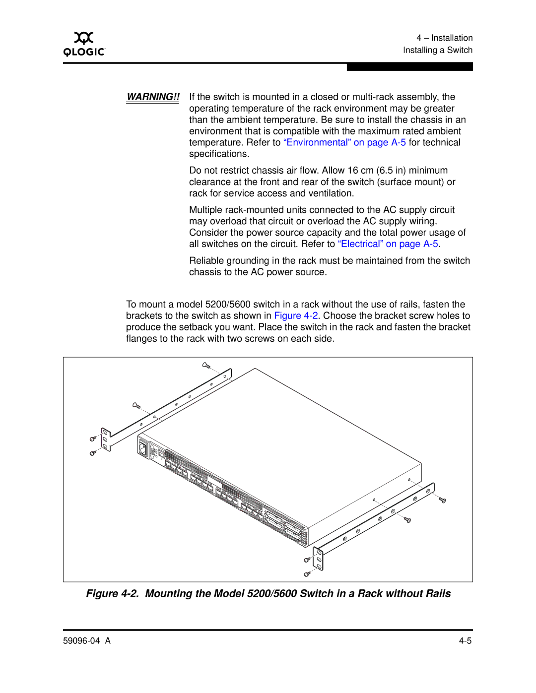
To mount a model 5200/5600 switch in a rack without the use of rails, fasten the brackets to the switch as shown in Figure 4-2. Choose the bracket screw holes to produce the setback you want. Place the switch in the rack and fasten the bracket flanges to the rack with two screws on each side.
L | 0 | | | | | | | | | | | | | | | |
| | A | | | | | | | | | | | | | | |
| | L | 1 | A | | | | | | | | | | | | |
| | | | L | 2 | | | | | | | | | | | |
| | | | | A | | | | | | | | | | |
| | | | | | L | 3 | | | | | | | | | |
| | | | | | | A | | | | | | | | |
| | | | | | | | L 4 | A | | | | | | | |
| | | | | | | | | | | | | | | |
| | | | | | | | | L | 5 | A | | | | | |
| | | | | | | | | | | L 6 | A | | | | |
| | | | | | | | | | | | L 7 | A | | | |
| | | | | | | | | | | | | L | | | |
| | | | | | | | | | | | | A | | | |
| | | | | | | | | | | | | L | | | |
| | | | | | | | | | | | | A | | | |
| | | | | | | | | | | | | L | | | |
| | | | | | | | | | | | | A | | | |
| | | | | | | | | | | | | L | | | |
| | | | | | | | | | | | | A | | | |
| | | | | | | | | | | | | L | | | |
| | | | | | | | | | | | | A | | | |
| | | | | | | | | | | | | L | | | |
| | | | | | | | | | | | | A | | | |
| | | | | | | | | | | | | L | | 16 | |
| | | | | | | | | | | | | A | L | |
| | | | | | | | | | | | | L | A | | |
| | | | | | | | | | | | | | A | 17 | |
| | | | | | | | | | | | | | L | |
| | | | | | | | | | | | | | A | | |
| | | | | | | | | | | | | | | L | 18 |
| | | | | | | | | | | | | | | A | |
| | | | | | | | | | | | | | | L | 19 |
| | | | | | | | | | | | | | | A | |
Figure 4-2. Mounting the Model 5200/5600 Switch in a Rack without Rails