A
4 – Installation Installing a Switch
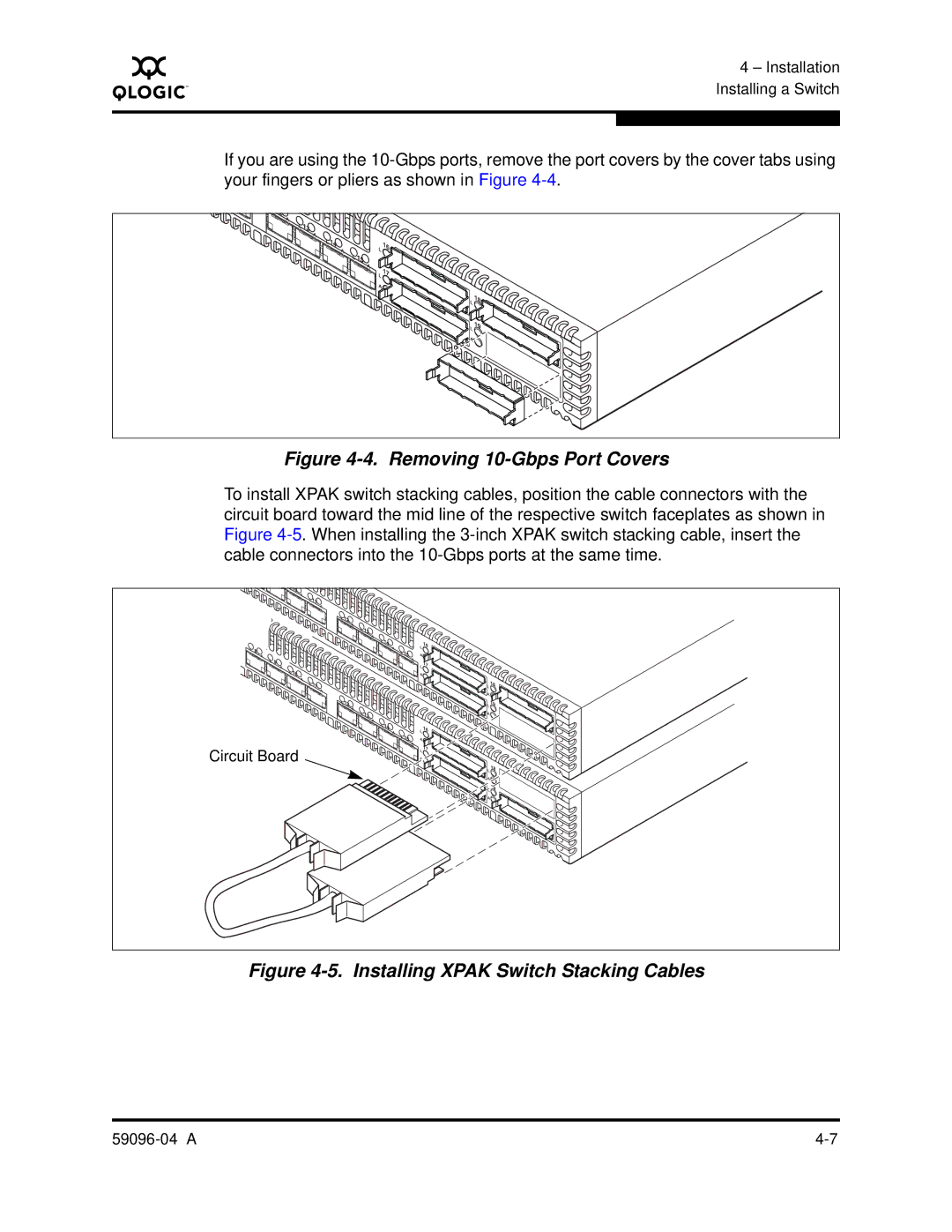
If you are using the
A |
|
|
|
|
L |
|
|
|
|
A |
|
|
|
|
L |
|
| 16 |
|
A |
| L |
| |
L |
|
| ||
|
|
|
| |
| A |
| 17 |
|
|
| L |
| |
|
| A |
|
|
|
|
| L | 18 |
|
|
| L | 19 |
|
|
| A |
|
Figure 4-4. Removing 10-Gbps Port Covers
To install XPAK switch stacking cables, position the cable connectors with the circuit board toward the mid line of the respective switch faceplates as shown in Figure
L |
|
|
|
|
|
A |
|
|
|
|
|
L |
|
|
|
|
|
A |
|
|
|
|
|
L |
|
|
|
|
|
A |
|
|
|
|
|
L |
|
|
|
|
|
| A |
|
|
|
|
| L |
|
| 16 |
|
L | A |
| L |
| |
L |
|
|
| ||
A |
| A |
|
| |
|
|
|
| ||
L |
|
| A |
|
|
A |
|
| L |
|
|
L |
|
| A |
|
|
A |
|
|
|
| |
|
|
|
| 18 | |
L |
|
|
| L | |
A |
|
|
| ||
|
|
| A |
| |
|
|
|
|
| |
L |
|
|
| L | 19 |
A |
|
|
| ||
|
|
| A |
| |
L |
|
|
|
| |
| A |
|
|
|
|
| L |
|
| 16 |
|
| A |
| L |
| |
| L |
|
| ||
|
| A |
|
| |
Circuit Board |
|
| A | 17 |
|
|
| L |
| ||
|
| A |
|
| |
|
|
|
| 18 | |
|
|
|
| L | |
|
|
|
| A |
|
|
|
|
| L | 19 |
|
|
|
| A |
|